Motivation
There is a conventional printer that moves paper to move and ink that moves across the printer. Also there has been project that prints using motors and two string, XY plotter. But, what if a robot moving around on a paper on your desk and start to draw a picture? This was to create a robot from a scratch and be able to draw a crude image of any picture.
Hardware
We are two ECE students who had no mechanical engineering or any robot related project team. As discussed in [Concern] Tab, we did not have the best implementation of the robots, we will discuss why we chose the design we have.
Overview
An easiest way to build a robot is to use an already built RC car. It is sturdy and reasonably accurate in motion. However with budget of $75, we could not purchase a RC car. Instead, we decide to build a robot from the scratch to meet our requirements.
Requirements
•Accuracy
•Must be able to turn in place (or at least 90° turn)
•Hold pen and must be able to lift it up fast
•$75 budget
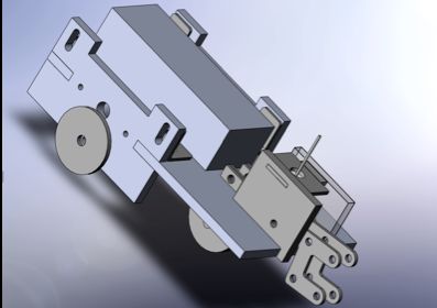
We have used Rapid-Proto-Typing to make bodies and basic structures easily. After simply designing parts with Solidworks, we can use laser cutting on acrylics to produce reasonably accurate parts. Also the Rapid-Proto-Typing was very favorable since we do not have any machining experience and mechanical professor had let us use the machine without any cost.
Our largest concern was the motor implementation. DC motors are very easy to use but it is very inadequate for system that requires accuracy. In terms of accuracy, the servomotors are very favorable, however, the cheapest servomotor cost about $15 and it takes significant part of the budget. Instead of servomotors, we had chosen a stepper motor, which is accurate enough for our use and it was very cheap (we had scavenged it from previous project).
How can we rotate a body by 90° with minimum number of motors (since number of motor is limited by budget)? This is a question that we had struggled to find an answer. The rotation motion is crucial since any error can lead to a larger error after long run of drawing. Robot can be indifferent of its sensitivity to error if there is a feedback system. Originally we had decided to use optical mouse sensor as a feedback system but we had failed to decode PS/2 communication initialization of the optical mouse sensor. The most sensible answer to the question is using two stepper motors to rotate in different directions.
While scavenging previous projects, we had found very interesting part, a solenoid (191172-001). Current induced through the solenoid pushes the pin of the solenoid while pin becomes loose without any current. Using these characteristics, we built a simple lever system that goes up when pin is pushing.
Software
There are two main softwares: one is Matlab and another in MCU. The software on Matlab part provides a GUI to a user that allows the user to select a picture and execute the robot to draw crude version of the picture. Matlab and MCU communicate using RS232 serial port.
Matlab GUI
Picture Processing & Instruction Generation
When a user loads a picture, our software samples 64×64 linearly spaced points. Unlike an inkjet printer, we cannot control the nozzle on the ink, but instead we are using pen or a pencil. Since we cannot express the coloring, we have crudely estimated RGB to 0 for values lower than 64, 255 for values greater than 192, and 128 for values in between. After sampling, software begins to generate series of the instruction. Before explaining generation of the instruction, we need to discuss limitations of the hardware.
First the precision is a large drawback of our design. For couple of weeks, we tried utilizing the optical mouse as a feedback system. But as due date for the project comes near, we could not open PS/2 communication between optical mouse and MCU; however we have strong sense of what to do.
Precision without a feedback system is very delicate. Although this concern is mentioned in the hardware part, we had implemented two independent wheel operations for movement and one dummy wheel to support the structure. We had reached this conclusion in part because of budget, which limited our purchase of motors, and we wanted a rapid 90 degrees turn rather than a gradual turn. If we were to draw two parallel lines separated by 0.1 inches we need to turn 90 degrees at the end of the first line, move 0.1 inches, and then turn another 90 degrees to start the second line. In order to execute these series of rotation, we rapid turn is more precise than gradual turn.
This delicacy of the hardware made it virtually impossible to make intricate instructions to draw arcs, circles, or a flexible image. Instead we decided to do straight lines approach. In the movie “I, Robot,” there is a scene when a robot sketches its dream and the sketch was drawn using only horizontal lines.
Writing an Instruction Making method was not too hard after all. A general idea is if there is color on consecutive horizontal data points, it will draw a line and if there is no color, then it will just move. When the robot reaches end of the sample (index of either 0 or 63), then it will have series of rotation instructions described above.
GUI
In order to achieve good user interface, we had developed a simple GUI using GUIDE function of the Matlab. A great advantage of using GUI is it is an event-triggered interface. Event-triggered nature of GUI is very useful while Matlab is sending instructions to the MCU.
When the Matlab side of the program is transmitting instructions, it is in a while loop for instruction transmission and transmission validation. Also there is a case when robot’s memory is full (will be discussed below in MCU) when robot cannot take further instruction and Matlab has to wait in a while loop to check status of the robot. In either case, the transmission of the data defers any user intervention.
However like Lab 3, Security System, concurrency is a priority in this system. For instance, even if robot is behaving oddly, a user should be able to easily stop immediately. Also robot must be able to start at any instance when user sends a correct command.
If the User Interface was written in a simple function, above blocking loop may have made the concurrency impossible. But we made our own command window, which is based on callback.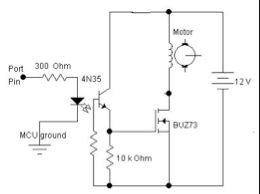
Extra: Instead of user setting COM Port manually, our GUI detects usable port and fills in the box below. However there are times when serial port is locked or need special setting and in that case, the GUI asks user to manually type the name of the port and makes a connection.
parts List:

For more detail: Robot Plotter Using Atmega32