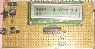
The 10k potentiometer, just above the ISP connector near the lower middle of the board, is used to adjust the display contrast according to your vertical viewing angle.
DOWNLOADS
ATTINY2313/AT90S2313 AVRStudio assembler source.
UPDATED FOR COMPATIBILITY WITH NEWER VERSIONS OF THE ASSEMBLER. LDCbutons040904C_updated_a.htm
Truly LCD driver include file. 2x16lcdinc.htm
tlcd309Ba.htm AT90S8515/ATMega8515 AVRStudio assembler source by Rafael A. Alcocer.
Original version of posted AT90S2313 code in zip archive tlcd030929A.zip.
Note on hex files and source code:
The 040904C version of the code has a larger UART receive buffer and supports two pushbuttons that send either and ASCII “R” ($52) or an ASCII carriage Something to keep in mind when using AVR controllers that support 16 bit addressing(specifically, the ATTINY2313/AT90S2313 only has an 8 bit stack pointer, while some others have 16 bit stack pointers) found by Rafael A. Alcocer has been taken into account in version ATTINY2313AT90S2313 version 030929A as well as being incorporated into the ATMEGA8515/AT90S8515 version. This code should be able to run on the ATTINY2313 without modifications, as well as the other AVR controllers with appropriate modifications for things such as clock speed and I/O port assignments.
The Truly MTC-C162DPLY-2N-LCD is an inexpensive two line LCD display and seems to be ideal as a display for some of my projects that have serial data outputs. Before building this interface, I used to either have a computer on the workbench to serve as a terminal or run an RS-232 cable from the desk with the computer on it to the workbench. When I saw the backlit version of displays being offered for less than US$6.00, I thought “Why not?”.
The Truly display uses the Samsung KS0070B controller, which is (reportedly) compatible with the Hitachi HD44780 controller. I found a set of initialization and control routines that were written and placed on the on the web by Richard Hosking which only required a minor adjustment to get the Truly display working. Mr. Hosking’s code was used in the assembler code that was originally posted and is in the ATMega8515 version. Mr. Hosking’s code served as a model for the .include file driver that is used in the current AT90S2313 version.
The main minor adjustment I mentioned in the paragraph above was the addition of a second “Function Set” command that was needed to get the Truly displays to work. Mr. Peter Coppens has reported that he had to remove the second “Function Set” operation in the initialization routine in the Truly LCD Include file. This is noted in the include file by labeling the two lines with the comment “(OMIT FOR HITACHI)”. the affected code fragment is shown immediately below (Some white space removed for to better fit on this page)..
ldi     temp,0b00101000	;Function set 4 bit mode, 2 lines 5X7 pixels.
rcall   SendCommand	;Write to display -first write sets 4 bit mode.
ldi     temp,0b00101000	;Function set 4 bit mode, 2 lines 5X7 pixels	(OMIT FOR HITACHI)
rcall   SendCommand	;write to display -second write to set N and F	(OMIT FOR HITACHI)
With this arrangement, the Truly display has a 4 bit parallel interface. TheATTINY2313/AT90S2313 controller converts incoming serial data to the appropriate 4 bit parallel commands and data. Incoming characters are written to the bottom line of the display and when a displayable character, that is a character that is not a control character, is received after a linefeed is received, the bottom line is copied to the top line, leaving a blank line on the bottom with the cursor set to the first column of the bottom line.
This delayed implementation of the linefeed until after a displayable character is received keeps the display from scrolling at the end of a line until there is something to display on the next line, thus two lines of information are always displayed, even when using it with hardware that automatically sends a carriage return and linefeed at the end of each line. This is important when you only have two lines on the display.
It should be noted that the LCD display interface code is copyrighted by Mr. Hoskin and on his web page, we are admonished to use the code for personal use only. The rest of the code is hereby placed in the public domain.
When using the circuit (below) with 0 to 5V level serial connections, doide D1 and capacitor C1 may be omitted and the lower end of R1 connected directly to ground (see the schematic, below).
For more detail: Serial interface with 2X16 LCD display using ATMega8515 microcontroller

