Generally we know about interfacing button switches, LED with Atmega32 microcontroller. We know that interface switch’s to one port, LED’s to another port and if we press any switch the corresponding LED will glow. But all the LED’s operate with single switch we don’t know.
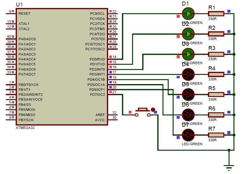
Here we are developing the program for operating 7 LED’s with one switch. The circuit connections and programming is so simple. We will discuss here about that. First we see the circuit connections. Let us take any one port of Atemga32 controller is PortD. Connect 7 LED’s to PortD and connect on switch to remaining pin of the PortD as shown in circuit diagram.
Now let us start the coding for microcontroller. First open the Atmel Studio software of any version. Create a new project with your desired file name. Here I am taking the project name as “button switch”. In the text window type the program mentioned below and we will discuss each step clearly.
#include<avr/io.h>
#include<util/delay.h>
These are the header files for Atmega32 microcontroller main function and delay function.
void pressedbutton (int a);
void releasedbutton (int b);
This is the prototype declarations for the code blocks. These are mentioned at the beginning of the program. One is for button pressed and another is for button released. Next thing ‘a’ and ‘b’ are the two integer values. We don’t know which button is pressed, so ‘a’ stores the button pressed value and as same like ‘b’ also. We don’t know which button is released, so ‘b’ reads the released button status.
int pressed_level[1];
int released_level[1];
int pressed[1];
int lednumber[1];
This is the declaration of the global variables. The variables are represented in arrays because number represents the capacity of the array. If we want to increase the buttons the array size may change according to our requirements. For example we need to add two buttons for two ports and operating the 14 LED’s we need to replace 1 with 2. Here ‘pressed’ is the global variable to store the status of pressed button. Declaring the new variable as lednumber which can represents which LED is in on position.
Next about main function, we will have much aware about main function right…, next port initialization. Here we are taking PORTD among form the four ports. In PORTD from pin0 to pin6 we are declaring as outputs because we are interfacing LED’s to these pins only and pin7 is declaring as input because the button is connected to this pin only.
DDRD = 0b01111111;
PORTD = 0b10000000;
The above statements represent the port initialisation ‘0b’ means representing in binary values. Instead of ‘0b01111111’ we can represent with 0X7F also. The only difference is number format ‘01111111’ represents the binary value and ‘0X7F’ represents the hexadecimal value. In data direction register ‘0’ represents the input and ‘1’ represents the output. So in PORTD 7th declared as input and ‘0 to 6th’ pin declared as outputs and by using the PORT register all the pins ‘0 to 6’ make as output low and 7th pin as input high.
while (1)
{
}
This is loop condition that executes the condition infinite number of times.
For more detail: Switch Status & LED with AVR microcontroller
About The Author
Ibrar Ayyub
I am an experienced technical writer holding a Master's degree in computer science from BZU Multan, Pakistan University. With a background spanning various industries, particularly in home automation and engineering, I have honed my skills in crafting clear and concise content. Proficient in leveraging infographics and diagrams, I strive to simplify complex concepts for readers. My strength lies in thorough research and presenting information in a structured and logical format.
Follow Us:LinkedinTwitter