Some time ago, I stumbled upon an article about 25¢ I²C adapter. I usually use my Raspberry Pi to interface with I²C devices, but having it right on my notebook seemed like quite useful thing, so I decided to build a project around it.
Probing
Altough the mentioned article says that I²C is not supported on Intel cards on Linux (all of this was tested on Dell Latitude E5530 which does have Intel HD4000), I decided to try anyway. A lot has probably changed since 2008 when it was written.
Well, this means I have 9 I²C buses available on my box (with this kernel at least). Maybe there are some interesting devices already there?
Sadly, not much. Only device present is at address 0x50 on bus 2. This is usually SPD memory on the RAM module. There is kernel driver in drivers/misc/eeprom/ and i2c-tools userspace tool decode-dimms if you want to play with this more.
Anyway, one of the buses should be on the external VGA connector, so let’s just use logic analyzer to determine, which one it is.
The bus number 1 turned out to be the correct one.
Board
Design
One of the problems (or features) with the built-in I²C bus is, that it does have internal 5V pull-up resistors. This is only useful as long as you do not want to talk to lower voltage devices.
Because of that I decided to make board with VGA connector and level shifter. Because I had a few Atmega328s around from previous project and they were not of any more use, I added one on the board as well to serve as a GPIO expander + LED driver. You can never do anything wrong with several LEDs.
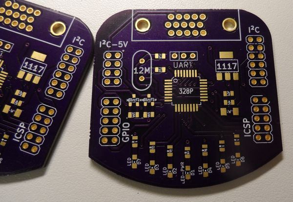
After a few hours, this was created:
The AVR runs on 12MHz crystal (just on the edge of what it can handle at 3.3V) and does have 4 LEDs connected to its PWM channels + 10 GPIOs on one of the external headers (2 more LEDs are connected to GPIO0 and GPIO1). There is also one LED for power indication, but in the final build, this one was left unpopulated. As for the I²C, headers for both 5V and 3.3V lines are in the top left and top right. 8-pin ICSP header is used to load code into the Atmega. UART in the middle is for debugging/bootloader if that is ever needed.
For more detail: TWILight – VGA I²C breakout board