Introduction
Many digital artists draw with mice on computer or use tablets. However, tablets are often very expensive. Using the mouse is not always as accurate and one needs a steady hand. Our project attempts to create a lower budget alternative to the tablet that is easier to draw with. We use a stack of magnets to act as a pen on pad. Hall sensors detect the location of the magnets, and the information is sent to the computer through USB. Pushbuttons are used to act as mouse buttons.
High Level Design
Rationale and Logical Structure
Human interface devices(HIDs) have integrated themselves into our daily lives. First, there came PS-2 keyboard. Then came serial keyboard and mice. The current technology is USB keyboards and mice. (Most laptops nowadays only have USB ports.)
Digital art is also very popular, used in movies and other forms of entertainment. Some artists, both expert and beginners, work with digital art through mice or tablets. However, tablets are expensive and not always within budget. The mice are not always accurate to use for those with shaky hands. The tablets pen, on the other hand, is more accurate since it mimics the shape of a pen with a clearly defined pressure point.
Since we dont have the budget to buy tablets, we decided to make an alternative, a low resolution USB magnetic based mouse. We chose to use USB because it is the most compatible with computers. We decided on magnetic since we wanted to try out Hall effect sensors for distance.
The mouse moves and operates based on the users actions. Left clicks and right clicks can open documents and change properties on files. When the user moves the mouse, the mouse will move as well in the same general direction. The direction and displacement of the mouse is based on relative motion not absolute motion. How much the mouse moves depends on how fast the user moves the mouse. If the user moves the mouse faster, the mouse will move a greater distance. Likewise, if the user moves the mouse slowly, the mouse will move a shorter distance.
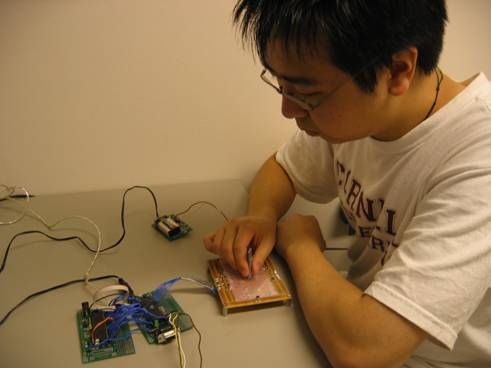
Our project can be split into two parts; the USB component and the mouse component. The data from the mouse component is sent to the USB component, which transfers the data to display on the computer. (The gray cable was used to connect to an STK500 board to program our chips. The serial connector is for testing purposes when we used Hyperterm.)
The USB apparatus is a USB connector connected to a programmable board with Atmel Mega32 chip. The board is powered by the VCC of the USB connector. The wires going into the MCU are data inputs coming from the mouse MCU outputs; relative X/Y displacements and pushbuttons.
The mouse component is more complicated. It also uses a board with an Atmel Mega32 chip (powered by a power supply). Wires from PORTB and D go to the USB component as input data. The three pushbuttons (left click, right click, and draw option) connect to the chip. Another bigger soldered board holds six Hall effect sensors and acts as the drawing pad. To draw, the magnets(held together by duck tape) are moved across the pad, and the sensors detect the magnetic field data. The push buttons act as left and right mouse buttons. The battery powers the Hall sensors and grounds the MCU. We decided to use a battery since it gave us less fluctuating results for the sensors.
Background Math
The background math used in this project was used to determine location of the magnets on the drawing pad.
Trilateration uses at least three reference points to determine the location of an unknown point on a 2D plane. Since our voltage distance relationship is not linear, we could not locate reference points and determine the unknown point and use this method.
Triangulation also uses three reference points and uses triangle lengths to determine the location of the unknown point. We also could not use this method for the same reason as trilateration.
Bilinear Interpolation consists of two linear interpolations, one in the x direction and one in the y direction and is used to find the location of a point in between four known points. The following equation from Wikipedia explains the relationship between the points. F(0, 0), F(1, 0), F(0, 1), and F(1,1) are the four known points. F(x,y) is the unknown point. In our case, we used ADC values from our Hall sensors and our calibration points to solve for x and y with multiple forms of the equation.

First Norm is the sum of the absolute values of difference between the numbers.
Second Norm is commonly known as the distance formula in mathematics.
Hardware/Software Tradeoffs
We really didnt have any tradeoffs. The only alternative was to use a serial USB connector hooked up to the mouse MCU instead of modifying USB code to use on another MCU.
Standards and Copyrights
The only standard that applies to the project here is the USB 1.1 standard. The source of our AVR USB HIDKEYS code is an open source licensed as the GNU General Public License Version 2 (GPL2) and can only be used for educational purposes with “OBJECTIVE DEVELOPMENT GmbH.
Program and Hardware Design
Hardware Design
We soldered and built the our two protoboards following Professor Bruce Lands guidelines. We soldered on pins to the board instead of our wires and chips for convenient replacement.
The Hall sensors are about 1.3mV per Gauss. To detect anything, we needed an amplifier to make the signal readable by the ADC. The Hall sensors were also bipolar, and we wanted them to be unipolar. So, we needed a reference difference of 2.5V.
To get the same amplification for our sensors, we needed a fixed gain differential amplifier. Resistors by themselves are not accurate and can differ 5% from each other, so we used resistor packs to decrease the error. We used the resistors in the packs in parallel to get 2.5V. We found that using a battery power instead of a power supply resulted in less noise from Hall sensor values.
The output of the differential amplifier goes through a low pass filter to with capacitance of 1F and 51k ohm resistor. This takes care of the high frequency noise, but allows the Hall sensor data to go through.
Parts List:
| Part Name | Number | Total Price | Source |
|---|---|---|---|
| D42-N50 Magnets | 10 | $3.20 | KJ Magnetics |
| Atmel Mega 32 | 2 | $16.00 | Bruce Land |
| MP 120 (12 Hz Crystal) | 1 | $0.94 | DigiKey |
| 9V Battery | 1 | $2.00 | Local Grocery Store |
| Custom PC Board | 2 | $10.00 | Bruce Land |
| Solder Board | 1 | $2.50 | Bruce Land |
| Power Supply | 1 | $5.00 | Bruce Land |
| RS232 Connector | 1 | $1.00 | Bruce Land |
| FreeScale Board | 1 | Sampled | FreeScale |
| 9 volt battery clip with 3 and 5 volt regulators | 1 | Sampled | FreeScale |
| MAX232 | 1 | Sampled | Maxim |
| A1302EU-AT (Linear Hall Sensor) | 6 | Sampled | Allegro |
| Max4462 (Diff Amps) | 6 | Sampled | Maxim |
| Pushbuttons | 3 | Already Owned | Yiyin Ma |
| USB Cable | 1 | Already Owned | Yiyin Ma |
| Plastic CD Case and Foam | 1 | Already Owned | Yiyin Ma |
| Total: | $40.64 |
For more detail: USB Magnetic Mouse/Touchpad Using Atmega32