This article is in continuation to AVR interrupts. There are two types of interrupts external and internal in AVR microcontroller. The aforesaid article covers external interrupts. AVR microcontrollers have seventeen internal interrupts. These internal interrupts are generated by the internal peripherals of Microcontroller like Timer, ADC etc. The internal interrupts are used for efficient operation of the internal peripherals. This article explains the internal interrupts using the example of an ADC interrupt.
Each internal peripheral system consists of one IE (interrupt Enable) bit which activates the internal interrupts of that peripheral. For example, in-built ADC of AVR consists of ADIE (ADC interrupt Enable) bit in ADCSRA register.
In addition, the I-bit of SREG is also activated to activate interrupts. SREG is a status register of AVR microcontroller which contains information about the result of most recently executed arithmetic instructions.
SREG (Status Register):
Bit 7-I: (Global interrupt Enable):
To activate Global Interrupts this bit must be set to high. If this bit is not enabled, none of the interrupts will work. “sei ()” command is used to enable the Global Interrupt, and “cli()” command is used to disable global interrupt.
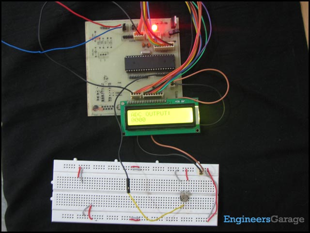
For better clarification of internal interrupts, ADC interrupts is explained below:
ADC interrupts:
In the article of AVR ADC, polling method is used to receive converted value. During the polling of a signal, microcontroller cannot perform another task. Hence, it is better to use interrupt method. ADC system consists of ADIE bit in ADCSRA register. ADIE bit is enabled to use ADC interrupts.
ADC in auto-triggering mode:
In A/D conversion ADSC bit remains high till the conversion is not completed. As soon as the, conversion gets completed, ADSC automatically gets cleared by hardware. Before starting the next conversion, ADSC must be set high again. Alternatively, auto triggering can be used to enable the ADSC bit after each conversion. The ADATE (ADC Auto Triggering Enable) bit in ADCSRA register is used to activate auto-triggering mode. There are various triggering options available in AVR ADC, which can be selected by configuring ADTS (ADC Triggering Select) bits in SFIOR register.
For more detail: How to use internal ADC of AVR microcontroller using interrupts