Introduction
We decided to create a virtual archery game for our ECE 4760 final project. This game consists of an ATmega1284P microcontroller, a TV for display, and multiple pieces of hardware. All of these devices communicate together to simulate a three-round game of archery with a target that is 20 feet away from the user.
The ATmega1284P microcontroller uses its internal analog-to-digital converter (ADC) to determine when the stretch sensor has been drawn and released, communicates with an external ADC over SPI to obtain the orientation of the bow from an accelerometer, and displays the expected location of an arrow fired by the user. Another arrow is readied by the push of a button on the bow. When the bow is fully drawn, LEDs will light up simulating the arrow. The lights are turned off when the arrow is released.
This game was inspired by the archery in The Legend of Zelda video games. We wanted to create an archery game that could re-create the fun that we had playing The Legend of Zelda, but that was also safe and convenient.

High Level Design
Rationale and Sources
Archery is a fun sport that we were interested in, but having to carry around and shoot arrows can be unsafe and inconvenient. Finding an appropriate location to practice archery could also difficult and pricey. Virtual archery is a fun way to solve some of these problems. By incorporating the physics of a traveling arrow and knowing the height and distance of a target, a person can simulate the arrow hitting the target. This will allow the person to have some basic practice on how to aim a bow and hit a target.
Since this game was also designed for our culminating design experience (CDE) course, we wanted to incorporate a variety of different topics. We decided to use a stretch sensor to simulate the bow string since it would change resistances based on how far back we stretched it. Creating a voltage divider with this made a simple and effective way to determine the length at which the bow string was stretched. Using the accelerometer also seemed like the simplest way to determine tilt, which was necessary in the calculation of the physics for the system. The TV also had a straight forward RCA connector that would make it easy to connect to and display our target. Since we didn’t have to display any moving objects we knew that flickering would not be a problem. This seemed to make using the TV the most effective solution for a display. After trying to meet our requirements using the most effective and diverse solutions, the layout for our project simply came together.
Background Math
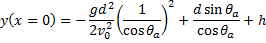
An arrow flying through the air can be modeled as a simple projectile. By defining the center of our coordinate system at the center of our target, it is relatively simple to develop a set of equations to map several input variables into positions on the target. In the vertical direction, we simply start with acceleration due to gravity and integrate twice to find the arrow’s position at any time. In the horizontal direction, we begin with the horizontal component of our initial velocity and integrate once. With both horizontal and vertical positions known in terms of time, we solve for the vertical position in terms of the horizontal position, and then the vertical position at the target.
In order to simplify our design, we fixed many of our values. The distance from the target is set to 20 feet, while the height above the center of the target is assumed to be zero. The initial speed of the arrow is then set to 180 feet/s, which appears to be a reasonable speed for an arrow fired from a standard bow. The remaining variable is the initial angle of the bow, which can be determined from the accelerometer.
The purpose of an accelerometer is simply to measure accelerations in one or more directions. Because gravity is a constant acceleration in a constant direction, an accelerometer can easily be used on a stationary object to determine tilt relative to the surface of the Earth. Our accelerometer is set such that it measures 1 g of acceleration when pointing straight down, and 0 g when parallel to the ground. Because this system is circular, the relation between angle and measured acceleration is:
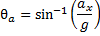
Now that we have derived an equation that can match our measured inputs to our unknown variable, we combine our equations. When we do, the trigonometry cancels out and we end up with:
 ,
, 
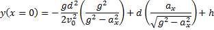
This equation is now simple enough that, even without fixing many of the values, it could be evaluated in real-time on a microcontroller. However, because our setup calls for only one independent variable, we decided that it was simpler to generate a lookup table of values that fall on the screen. One further layer of math was added during this step to relate the actual reading from our accelerometer to the acceleration, and thus the output. This relationship was determined by our hardware setup and the specifications of our ADC’s datasheet.
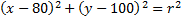
In order to draw the target, four concentric circles needed to be drawn. This required us to use the equation of a circle:
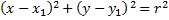
The x1 and y1 terms are used to center the circle around a particular (x,y) coordinate. In this case, the coordinate (80,100) was a good center for our target. The equation is now modified to:
After this, we created a look-up table for all the possible y values within the radius of each circle. This would let us avoid doing slow math, potentially messing up the timing of our TV. The following equations are solved for y:
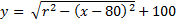
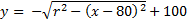
Since we are taking the square root of a value, we need to worry about both the positive and negative values of the equation. These will represent the bottom half and top half of the circle respectively.
Logical Structure
The three major pieces of the archery system were the LCD television, the accelerometer circuit, and the stretch sensor.

In order to function with the LCD television, or in fact any television operating on the NTSC standard, the microcontroller must continually generate a video output. The code to do so is adapted from previous labs performed during ECE 4760. An interrupt is triggered precisely once per video line and the bits to generate the image are sent out of the UART. This code takes up a large portion of the microcontroller’s processing time and prevents other interrupts from being used, which constrains some of the other code needed to run the system.
The accelerometer is a sensor that changes acceleration into a signal that can be used in an electrical domain. Our particular device outputs a voltage that is proportional to the magnitude of the acceleration. To use this acceleration in our program, this voltage had to be converted into a digital form. We chose to use an external ADC for two reasons: 1) the physical distance between the accelerometer and the microcontroller is very large, significantly increasing the potential for noise to corrupt the signal, and 2) the precision of the on-board ADC is only 10 bits. We chose to sample a 13-bit differential ADC, which returns a 2’s compliment value via SPI. The negative input was set to roughly remove the offset of the accelerometer, and the reference was set roughly to Vcc/10 to increase the precision of the measurements.
The stretch sensor is essentialy a large resistor that changes resistance with length. The material is made up of carbon-black impregnated rubber with a resistance of about 350 ohms per inch. Since the stretch sensor is about 1 meter (39 inches) long, the total resistance of the stretch sensor is about 13.65 Kohms. As you stretch out the stretch sensor, the resistance increases linearly – about 350 ohms for every inch that it is stretched out. Once the stretch sensor is released, it takes some time to revert back to its original length. For our purposes, we only needed to wait about a second for the signal to get below our selected threshold.
Other miscellaneous pieces include the LEDs and the button. A bar/dot display driver is used to operate the 10 blue LEDs along the length of the drawback. Future modifications to this design could implement this driver in a way that the bar and/or dot modes are fully utilized – in our design, it is simply used in an on/off mode. The button is a simple pushbutton mounted to the bow. It is debounced in software.
For more detail: Virtual Archery using ATmega1284P