n our final project, we designed an electronic multifunction instrument with a LCD touch screen and a microphone. The user can play three kinds of instruments on it — xylophone, flute and piano. Each instrument has a different interface and timbre. The piano part has a record/replay function which can echo the song previously played on it. In addition, the system has another function to teach the user to play two pieces of songs already stored in the memory.
The LCD touch screen will display these three kinds of instruments — the keyboard of xylophone and piano and the holes of flute. User just presses on the keyboard to play the music. For the flute, the user need to press on the screen while blowing to the microphone, which simulates a real organ-like instrument. It also has record/replay and teaching functions.
The idea of this project came from some apps on the smart phone. It is very cool and popular to play a virtual instrument on the mobile phone, such as a guitar or a piano. People can take them everywhere and play on it whenever they want. With some knowledge about sound synthesis acquired in the class, we decided to build the electronic multifunction instrument in our project. Meanwhile, this project will also provide ECE4760 course a library for initializing LCD touch screens for reference. It also gives us experience in utilizing a set of devices which is popular in modern devices.
High Level Design
Rationale
It is quite meaningful for us to do this project. On the one hand, with the increasing popularity of touch-screen mobile phones and tablet PCs, touch screen becomes more and more important in our lives. It is much more convenient and flexible than the traditional keyboard. On the other hand, even though actual instruments have better tunes and player experience, they are always ponderous and hard to move or carry around. So it is very useful for us to play music only with a tiny and light box containing a touch screen and some electrical boards. Since we already owned a board with a touch screen LCD and relevant control chips on it, we came with the idea to implement a play-music function to the touch screen and also added some other functions talked above.
Logical structure
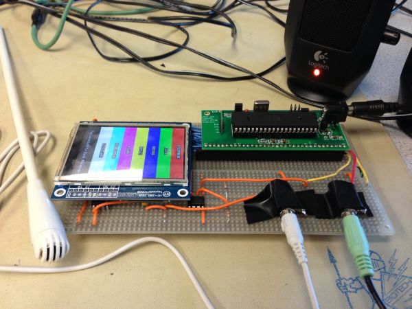
At the high level, our project mainly consists of four parts: the mega1284 microcontroller, the LCD touch screen, the microphone and the speaker. Mega1284 is the main control part. When user presses on the screen or blows at the microphone, the signal will be sent to the MCU and some certain sound will be played from the speaker. Also the MCU will control what is shown on the LCD screen and the state mode, based on the screen interrupt.
The connection between MCU and touch screen needs a LCD driver and an ADC chip. They are already on the touch screen board. An opamp is needed for the amplification of the input signal from the microphone. Then the MCU outputs the sound via an RC filter circuit. The high-level structure diagram of the system is shown below.
Hardware/Software tradeoffs
The hardware part of our project is not very complex. We already owned the touch screen and soldered our own Mega1284 prototype board. The LCD touch screen consists of two chips, ILI9325 LCD control chip and XPT2046 touch panel controller chip. The speaker and microphone are available in the lab. The only tricky thing is to convert the blowing signal to a continuous high-level voltage signal. We used two opamp chips to meet this requirement — LM386 and LM358, both are available in the lab. The total cost is surely under the budget.
For the software part, we thought it is pretty hard for the sound synthesis. So we tried both the FM and additive synthesis methods to get the idea effect. We also used the matlab program for the sound synthesis before implementing to the C code. For the touch screen part, we distribute the function into several modes. Each part we used some judgment and other codes to realize the function in the certain mode. It is not too hard to program and can be reliable.
Standards and Patents
Our design uses the SPI(serial peripheral interface) between the communication of touchpanel and AVR. Devices communicate in master/slave mode where the master device initiates the data frame. One patent is used in our design of FM synthesis algorithm. US3794748, Method of synthesizing a musical sound, by John M.Chowning in 1974, is where FM synthesis comes from. It is a research result of Stanford University.
Hardware Design and Implementation
Hardware Overview
From the high-level discussed above, our hardware consists of four parts, which include the LCD touch screen, the low pass filter circuit, the microphone input circuit and the Mega1284 prototype board. Below we will discuss each part separately.
LCD touch screen
The LCD touch screen we use contains of 2 parts, a 2.8 ” TFT LCD screen and the touch panel. The TFT LCD use the control chip, ILI9325, while the touch panel uses the Analog Device XPT2046 touch screen controller. (Figure of LCD touch screen). One of the reason we use LCD touch screen is that we can provide ECE4760 class some library for initializing LCD screen and touch panel.
ILI9325 is a 262,144-color one-chip SoC driver for a-TFT liquid crystal display with resolution of 240RGBx320 dots, comprising a 720-channel source driver, a 320-channel gate driver, 172,800 bytes RAM for graphic data of 240RGBx320 dots, and power supply circuit. By using this LCD, we can avoid some problem in our lab3, digital oscilloscope, that we need always refreshing the screen. The existence of GRAM in ILI9325 helps us to save the time in refreshing the screen. When we need to change what will be shown on screen, we just need to write the GRAM which replace the dots on the LCD.
Low pass filter and Speaker wiring
We also need a lowpass circuit to filter the PWM output. We decide to get RC= 1/10000 and set R= 5000ohm, which is lower than speaker input 10kohm. So C= 20nf. Actually we choose the 5.1kohm resistor and 20nf capacitor to build this circuit for the real value of the components. The INPUT is connected to the output of the PWM which is pin B.3 (OC0A). The OUTPUT is connected to the channel 1 in the plug of audio. The audio is shown below. Ground will be connected to the GND port on the board.
Microphone input circuit
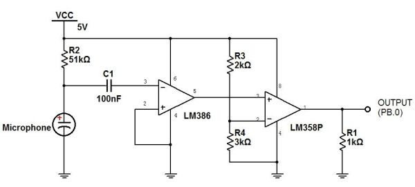
The microphone is used to capture the airflow from the player’s mouse to simulate the flute. According to the structure of the microphone, the sensor in the microphone will vibrate due to the frequency of the voice and so cause the change of the value of the capacitor in it. Thus the normal output of the microphone is like an irregular vibration wave. However, the purpose of the using of microphone in our project is only to detect the blowing wind, not the frequency. So we need to convert the output of the microphone to a high-voltage level when blowing and low-voltage level with no blowing. The circuit we designed for the input of the microphone is like this.
When we blow to the microphone, the voltage on C1 will vibrate. Since the amplitude of the vibration is much smaller than the static voltage, we need the capacitor C1 to separate the AC part and then use the LM386 (audio amplifier chip) to amplify the wave. We do not connect pin1 and pin8 on the LM386, so the amplification gain is 20. Then we use the oscilloscope to detect the output of LM386 and found it is between 1 to 3.5 volt with the static value equals to 2.2 volt. So we use the LM358 (comparator chip) and R3 and R4 to set the negative input as 2.7 volt( actually, the Vcc is a little smaller than 5V). So when we blow to the microphone, the output of LM386 could be greater than 2.7V and the output of LM358 will be high level, which can be detected by the microcontroller.
Note that R1 is used to make sure that the output is set low when there is no sound. Normally, R2 should be around 10kOhms. Because of the high current for the LCD touch screen. the Vcc may always been pull-down. That causes a wrong signal for the output. So we choose a big resistor with 51kOhms to limit the voltage vibration and it works. So in our flute design(below), we set a flag when we detect a high voltage. After a note is generated, we will clear the flag and wait for next high voltage of output.
Prototype Board
We build our own prototype board in the lab. The microcontroller and some peripheral capacitors and resistors are on it. The prototype board PCB is shown in the appendix.
Connection Board
In order to connect the prototypr with the touch screen board, we build this connection borad. The block diagram of connection is given in the appendix. The left 40-pins socket is for the prototype board and the right 20*2-pins socket is for the touch screen board. Also the low pass filter is also soldered on this board.
Software Design and Implementation
Overview
The most important part for the software design is the sound synthesis and the touch screen control. As described above, we devided this app into 6 modes
Parts List:
| Part | Unit Cost | Vendor | Quantity | Total Cost |
| Custom PCB (designed by Bruce Land) | $4 | Lab Stock | 1 | $4 |
| Atmega 1284 | $5 | Lab Stock | 1 | $5 |
| small solder board | $1 | Lab Stock | 2 | $2 |
| Power Supply | $5 | Lab Stock | 1 | $5 |
| 40-pin DIP socket | $0.50 | Lab stock | 2 | $1 |
| Header pins/plugs | $0.05 | Lab stock | 76 | $3.8 |
| Speaker | $0 | Lab stock | 1 | $0 |
| Microphone | $0 | Lab stock | 1 | $0 |
| Resisots | $0 | Lab stock | 6 | $0 |
| Capacitor | $0 | Lab stock | 2 | $0 |
| LM386 | $0 | Lab Stock | 1 | $0 |
| LM358 | $0 | Lab stock | 1 | $0 |
| 3.5mm Audio jack | $0 | Lab Stock | 2 | $0 |
| Wire | $0 | Lab Stock | 30 | $0 |
| LCD touch screen | $0 | Previously owned | 1 | $0 |
| Total Cost | $20.8 |
For more detail: Virtuoso: A Touchscreen Music App Using Atmega644