Introduction:
For our final project, we want to build a wireless drawing device. The user uses a keypad or a mouse to draw on the TV through a wireless communication medium (RF – 433.92 MHz). The user should be able to move the drawing pointer to anywhere within the four border lines. One should also be able to draw or erase images on the TV screen.
In designing this project, we have two goals – a primary, which is realizable, and a secondary, which is feasible. Our realizable goal is to build a wireless keypad interface with the television. In this interface, we want the keypad to be able to draw and erase on the TV. When we accomplish our primary goal, we shall attempt to achieve our secondary goal: to build a wireless mouse having the same functionality as the keypad. Due to time constraints, we ended up only being able to complete the primary goal. We chose this project because we were inspired by wireless communication technology.
Before we begin our design, there are some issues that we need to be be considered. There are two major parts to this wireless drawing device – a TV side and a keypad side. Therefore, there are two microcontrollers used: one for the TV side and one for the keypad side. The user interface (keypad side) of our drawing device consists of three buttons, left, right, and middle buttons, and a keypad or a mouse chassis. There is also a drawing pointer of size one pixel to ascertain where the drawing will occur on the TV.
Drawing Functions
There are three things that must be done in order to draw properly on the TV screen. The first is the drawing pointer movement. The pointer should be able to move up, down, left, right, and diagonally in all directions. The second thing is to draw on the TV screen. One needs to press the left button to draw wherever the drawing pointer is. Lastly, one needs to be able to erase the TV screen. One must press the right mouse button to erase wherever the mouse pointer is. If one presses the middle button, it will clear the TV screen and reset the drawing pointer to the center of the screen.
Wireless Communication
The connection is made via Universal Asynchronous Receiver and Transmitter (UART). We based our design on the Atmel Mega163 data sheet. On the keypad side, the microcontroller sends directional and button press signals to the transmitter via the TxD pin (PORTD.1), which is in turn received by the receiver on the TV side. These received signals go into the RxD pin (PORTD.0).
Also, the transmitter sends data at 433.92MHz. It has a maximum data rate to 4800bits/sec. We calculate the baud rate by using the formula given in the data sheet, UBR = fck/16(UBR+1), where fck is the crystal clock frequency. This UBR equation can be found in table 27 in the data sheet. For a 8MHz crystal, UBR = 103 will give a baud rate of 4800.
In order to get optimal transmission and reception, one needs to make the antenna approximately the size of one-quarter the wavelength of the transmitted signals. In our case, the wavelength is approximately 70 centimeters, and one-quarter of that is about 17 centimeters.
Basic Setup
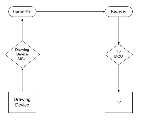
Our drawing device consists of three functions. The first function is the movement the drawing device. For a keypad, one can press keys 1 through 9 for directions. Examples of these directions are 1 is move up and left, and 6 is move right. On the TV screen, the drawing pointer will move in the corresponding directions. The second function is to draw and erase on the TV depending whether the left or right button is pressed. Lastly, we need to encode the button presses and directional movements into a signal and send the encoded signal to the television side via the transmitter-receiver pair. On the TV side, we then need to decode the received signal in order to show the graphic on the TV screen.
The basic hardware connection is shown below:
Materials used:
- 2 Atmel Mega 163
- 1 keypad
- 3 buttons
- 1 transmitter: RCT-433-AS from Radiotronix
- 1 receiver: RCT-433-RP from Radiotronix
- 1 TV
- 4 AA batteries
- Two 0.1uF,and two 27pF capacitors
- Two 0.01uF,and two 4.7uF capacitors
- Two 330, two 1k, one 160, and one 75 Ohm resistors
- One 3-terminal Positive Regulator: LM340
- One operational amplifier: LMC7111
Hardware Design
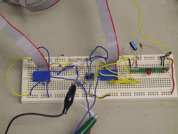
The hardware design for this project is slightly tricky. The hardest and most time-consuming part of this design was getting all the hardware parts to communicate properly with each other. Constructing the keypad side microcontroller design, an off-board microcontroller, was interesting.
We followed the diagram given on the Build your AVR Starter Kit page. We place one 27pF capacitor to pin 12 (XTAL2) and one to pin 13 (XTAL1) with a 8MHz crystal between those two pins. We place a 160 ohm resistor at pin 9 (reset’) to pull the reset’ to high to prevent constant resetting. Usually, reset’ does not require a pullup, but with the RF transmissions, there is added RF distortion on the chip, which requires the pullup at reset’. After many tries with different resistor values, we found that a 160 Ohm resistor gave the best result at pulling up reset’. This does cause a decent amount of current to be sucked from the battery source, but when we tried using a 10k Ohm resistor, there was still constant reseting. To program the chip Pins 6 to 11 are connected to SPROG3. Between Vcc and Gnd, there is a 0.1uF capacitor.
For more detail: Wireless Drawing Device


