I.Introduction
Soundbyte:A Wireless Data Telemetry system that receives acceleration, proximity and external temperature data from a remote vehicle and displays them on an NTSC television screen.
The rationale behind this project is to provide the user with information regarding the vehicles acceleration, proximity to other stationary objects, and external temperature. The information gathered would be useful if the vehicle is used to explore unfamiliar terrain. The vehicle is controlled by a small hand-held remote control with two joysticks (up, down, combination of both) that can make the vehicle go forward, backward and turn. The focus of the project was to design and build a wireless telemetry retrieval communication system that effectively communicates pertinent data using packets.
II.High Level Design
Our design consists of a microcontroller and several sensors mounted on the remote controlled vehicle to gather information about the vehicle and broadcast the information through a transmitter. The key focus would be to detect mechanical motions of the car and its surrounding conditions through the use of accelerometer, temperature sensor and infrared distance sensor. The information gathered is then encoded using a microcontroller and sent through a transmitter. At the receiver, we use another microcontroller to decode the received data packets and display the parameters on a TV.
Rationale and Sources of Project Idea:
We consulted several project websites from previous years to get an idea of what we can do with an RC car. We knew we wanted to incorporate a remote controlled vehicle as part of our design project. Our initial idea was to hack an RC car and implement additional features; however, after consulting Steve Lowe (one of the TAs for ECE 476) about the RC car he built, we decided it would not be worthwhile to try to find a non-existent spec sheet on a customized microcontroller chip within the RC car. Hence, we decided to leave the car as it is [much to the appreciation of Tiffanys sister whose car we borrowed] and design a stand-alone wireless communication system that would gather information about the vehicles surroundings.
Projects we consulted:
Background Math
There is very little background math required for this project other than the usual expected out of an ECE junior. The primary focus of mathematical calculations is the wireless communications: the data transfer rates, the timing, and the data encoding. Although background in Error Control Code theory would be helpful, it is not entirely necessary.
Logical Structure
Our design project consists of two major components, the car (transmitting end) and the home base (receiving end). The wireless telemetry system was designed as a stand-alone system consisting devices that can be attached to any moving object to detect its acceleration, surrounding temperature and distance from surrounding stationary objects.
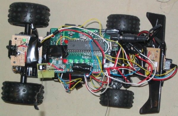
On the car (Figure Car.Block), we have several sensors to gather data from the surrounding environment and an AtmelMega32 microcontroller chip used to process the gathered data, which is then encoded into appropriate data packets and sent via the wireless transmitter at 433MHz. The sensor system on the car base consists of two temperature sensors (front and back), four IR sensors (two on the side, one front and one back) and one accelerometer (which measures both X and Y direction acceleration). We also included status LEDs on the CPU board to help with hardware debugging.
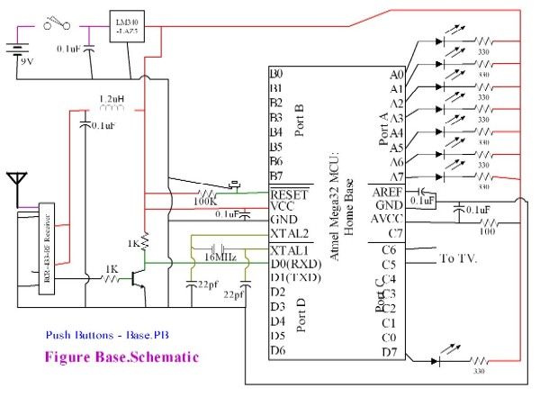
On the home base (Figure Base.Block), we receive the data packets from the transmitter via a 433MHz wireless receiver, and use another AtmelMega32 microcontroller chip to process and decode the received data packets. We then format and display the gathered data onto a TV screen. There is also a set of LEDs to facilitate debugging as well as make pretty light patterns to keep the user thoroughly entertained.
For the wireless communication network, we used radio waves (433MHz) to transmit and receive the data packets. Both the transmitter and receiver chips are mounted on the microcontroller boards. The receiver chip is soldered directly on the home base CPU board, the transmitter chip sits on a separate PCB board, but it attached to the car base CPU board. We consulted the spec sheets for design layout, overall the circuitries for the transmitter and receiver are relatively simple and straightforward to design and build. Professor Land suggested that we include a homemade inductor to deliver more power to the antenna, thus effectively increasing the range of the wireless transmission. The details of hardware design are explained in the next section.
Hardware/Software Tradeoffs
We built two customized PCBs for the two microcontrollers we used. We also built several separate pieces of Radio Shack through-hole solder boards that contain the circuitry for the analog IR sensor, temp sensor, digital IR/temp sensor and accelerometer. We also added 7 colored LEDs onto each CPU board for debugging purposes. Overall, our soldering and debugging efforts for the hardware portion of our project took up roughly 75% of our time. This is the first year that surface mount components were used in an ECE 476 final project, the customized CPU board was designed for this purpose. The surface-mount components we used this year made the circuitry a lot easier to maintain, we didnt have to deal with extra wires and large components with loose connections. As a result of using printed circuit boards, we had to solder under magnifiers and use extra fine tipped soldering irons to make the board. Nonetheless, it was a fun experience and a useful skill to acquire.
Following the logic of the hardware, the software was split up into two portions. Generating and debugging the software took a considerably shorter amount of time then getting the hardware working. Because our final project is so sensor centered, it is very hardware intensive. The software merely collects, manages and processes the data these sensors spit out; as long as the hardware works, the software is going to perform. Overall, the software occupied 25% of our times in terms of debugging and composing. Obviously the home base software took significantly more time than the car, for reasons explained in the software design section.
Professional Standards (FCC, UL, RS-170, RS-232)
There are several professional standards we must meet for our design project. We included them in the table below.
| Professional Standards | |
|---|---|
| Federal Communication Commission Standards (FCC) | Transmission frequency regulation |
| Underwriters Laboratories Inc. Listed (UL listed) | Electrical device safety |
| RS-170 | Black and white TV video format |
| RS-232 | Serial communication protocol |
Consumer grade remote controlled cars must meet the Federal Communication Commission (FCC) standards. The RC vehicle we are using for this project is an over-the-counter (OTC) consumer product; therefore we do not need to worry about conforming to the FCC standards (we assume that it already does). We are concerned with designing a wireless communication channel that meets the FCC standards. The remote controlled vehicle we used operates at 27MHz, the wireless communication network we designed operates at 433MHz; thus, the two operating frequencies do not interfere with each other.
In addition to the FCC standards, we conform to the Underwriters Laboratories Inc. Listed (UL LISTED) standards. UL listed standard is a set of testing standards for electrical equipments and products that assures its safety. In order for a product to carry the UL Label, the product must be independently examined and evaluated for safety. We believe that our device is safe to use, but it should be used responsibly. The stand-alone wireless communication system should not cause any harm or damage if operated under normal conditions and with precaution. However, we make no guarantees of safety, since the wireless communication system will be mounted on a radio controlled car, which might cause harm to small pets and children. We will try to avoid dangerous and potentially hazardous situations by not bringing pets or small children in the laboratory. Note that the voltage regulators tend to get hot and should be avoided when the system is in operation.
Since we generate TV signals as a part of our project, we must meet the RS-170 standard; which is the standard black and white video format used in United States (defined by 525 lines 30 frames per second). For the purpose of our project, we do not interlace signals, (instead of using interlaced refresh rate of 30 frames per second, we use non-interlaced refresh rate of 60 frames per second). Also, since we have limited memory available to us, we only use a 262 line scaling instead of a 525 line scaling.
We are using the RS-232 protocol to interface between the microcontroller and the wireless receiver and transmitter. The RS-232 protocol was developed to provide a greater distance for reliable serial communication via physical wire connection. It is mostly used as microcontroller-PC communication.
Relevant Existing Patents, Copyrights and Trademarks
Wireless telemetry system technology has many applications; it is especially well-suited for monitoring and controlling remote devices. Our wireless telemetry system is a modification of this generic technological concept (only monitor, no control), in that we sample and record data of the physical surrounding and send the data via a wireless transmitter. There are many existing telemetric systems in the market, we included the following websites for your reading pleasure. We assume the technologies featured in these websites have patents.
Parts list:
| Part Name | Model No. | Mfr. | Supplier | Qty. | Unit Price | Total |
| Atmel Mega 32 | ATMEGA32 | Atmel | Bruce Land | 2 | $8.00 | $8.00* |
| Custom PCBoard | BruceLand rev2 | PCB Express | Bruce Land | 2 | $5.00 | $10.00 |
| RF Transmitter | RCT-433-AS | Radiotronix | Mouser Electronics | 1 | $3.50 | $3.50 |
| RF Receiver | RCR-433-RP | Radiotronix | Mouser Electronics | 1 | $4.50 | $4.50 |
| IR Proximity Sensor | GP2Y0D340K | Sharp | Digikey | 1 | $8.03 | $8.03 |
| IR Proximity Sensor | GP2d12 | Sharp | Bruce Land | 1 | $0.00 | $0.00* |
| IR Proximity Sensor | GP2D15 | Sharp | Digikey | 2 | $0.00 | $0.00* |
| Temperature Sensor | TMP36GT9 | Analog Devices | Analog Devices | 2 | $0.00 | $0.00~ |
| Dual OpAmps | LM358N | Nat’l Semiconductors | Nat’l Semiconductors | 3 | $0.00 | $0.00~ |
| PC Board | 276-170 | RadioShack | Bruce Land | 1 | $2.50 | $2.50 |
| Dual PC Board | 276-148 | RadioShack | RadioShack | 1 | $1.79 | $1.79 |
| Accelerometer | ADXL202JE | Analog Devices | Bruce Land | 1 | $0.00 | $0.00* |
| JST Connector (M) | 455-1273-ND | JST, Inc. | Digikey | 10 | $0.115 | $1.15 |
| JST Connector (F) | 455-1126-ND | JST, Inc. | Digikey | 10 | $0.042 | $0.42 |
| IR Emitter/Detector | 276-142 | Radioshack | Radioshack | 2 | $3.30 | $6.60 |
| Other Lab Components | R’s, C’s, Wires | N/A | Bruce Land | 1 | $1.00 | $1.00 |
| *Salvaged from old projects, ~Sampled | TOTAL: | $47.49 | ||||
For more detail: Wireless Telemetry


