Introduction
“A composite personal health monitor solution bridges the gaps between patients and doctors.”
—Engineering Goodwill
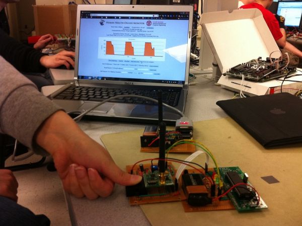
This project creates a portable device implementing wireless technology and taking full advantage of the wide-spreading Internet to provide a convenient solution to monitor human health. The health information acquired on the portable side transmits to the server wirelessly and can be accessed all over the Internet in real-time. The end product turned out to be very portable and the wireless connection is responsive and solid. A significant number of possible further implementations can be developed with minor effort based on this project. Eventually, this project provides a low-price, easy-access human health monitor solution bridging the gaps between patients and doctors.
High Level Design
Rationale
“Heart disease and stroke count up to 25% of all death in the world.”
“Every 33 seconds, a person dies of heart disease in the U.S.”
“90% of the death can be prevented if timely medical actions can be taken.”
Human health is an increasingly popular public concern. People spend tons of money on it because once get sick or dead, anything else becomes meaningless. Unfortunately, people always find that it is too late to receive serious medical care when things are already noninvertible. Lots of patients can be cured if early actions can be taken. However, the access to the medical equipment is inconvenient and expensive. Among the most important indexes of the human health, heart rate and body temperature are the most vital ones and they have the advantage of easy access. In addition, unlike the X-ray, the measurement of heart rate and temperature is extremely easy conduct and does no harm to human health itself.
In the current market, there are some personal medical devices which patients can use to do some basic measurement themselves. However, on one hand, since patients generally have little medical background, they have a hard time interpreting the medical measurement into meaningful diagnosis. On the other hand, delivering the raw medical measurement data to the doctors is time-costing and troublesome. Time can never be wasted when emergencies happen, it is critical if information can be shared on large scale coverage within a short of time. Most of the products in the market have these major drawbacks with limitation in flexibility and portability.
Functional Structure
Hardware/Software Tradeoffs
Wireless Communication
The alternative method which eventually implemented in the project is the wireless serial-232 communication. The cost the wireless transceiver is extremely low comparing with the Wi-Fi module with a price of 10 dollar each. However, as the old Chinese saying stated:” 便宜没好货,好货不便宜” pronouced as”pian yi mei hao huo, hao huo bu pian yi” and meaning “Cheap is with bad quality, good is with expensive price.” This cheap wireless solution provides an extremely low data rate up to 115.2Kbps. Fortunately, the slow rate is far more enough for the project which involved low intensity of data exchange. In addition, this module provides an easy-to-use USART interface which can take good advantage of the USART interface in the microcontroller.
Communication
Heart Rate & Breath Rate
Standards
UART
Software
Heart Rate Deteection Algorithmn
Cardiovascular Physiology Concept
The signal is cause by the cardiac cycle (See picture below). The following paragraph is excepted from www.cvphysiology.com which focuses on various cardiac diseases.
“As the left ventricle ejects blood into the aorta, the aortic pressure increases. The greater the stroke volume, the greater the change in aortic pressure during ejection. The maximal change in aortic pressure during systole (from the time the aortic valve opens until the peak aortic pressure is attained represents the aortic pulse pressure, which is defined as the systolic pressure minus the diastolic pressure. As the aorta expands, the increase in pressure is determined by the compliance of the aorta at that particular range of volumes. The more compliant the aorta, the smaller the pressure change during ventricular ejection (the Second small pulse (3)) shown in the following.”
First Version
To detect heart rate, the simplest thought would be using the output of the detection circuit as the input of a comparator and use a trimpot to set up the reference voltage of the comparator. The drawback of this approach is that the reference voltage has to be adjusted for each user because the signal from each user is different. Even for the same user, the signal could also have big variations. To make the detection smarter, the signal is sampled using an ADC and processed in the microcontroller.
Basic measurement method
As the first attempt, the signal is sampled at 50Hz. In order to judge whether this is a valid pulse, a threshold is needed and this threshold needs to be automatically adjusted according to the signal. Here, the algorithm of last year’s project “Heart Rate Display LED T-Shirt” is referred to. The average value of the previous 250 data points are used as the threshold. Two states are used: state low which means that the current state is below the threshold and state high which means that the current state is above the threshold. After a new ADC point is ready, the first thing to do is to check whether it is in the low state or high state. If the current state is high and the current data is smaller than the threshold, then it is a falling edge. A LED is turned off and the state changes to low. If the current state is low and the current data point is bigger than the threshold, then it is a rising edge. The LED will be turned on and the state changes to high. The time is recorded at this point. The time recorded for two consecutive valid pulses are to calculate the heart rate.
System status control
The pulse period for a healthy adult is 0.6 seconds to 1 second. If the tested period is not in this range, then it is regarded as noise. Otherwise, this is regarded as true signal. To measure the correct heart rate, the signal needs to be in a stable state. The criterion for stable state is defined as: if there are three consecutive pulses whose periods are within the predefined range, then the system enters stable state. Once the period of a pulse is not within the valid period range, then the system exits the stable state. In the stable state, the average of three consecutive periods, N (in points), is used to calculate the new heart rate. The range of period for valid pulses is then updated as N-10 to N+10 in points. In order to tell the user that the signal is stable and valid, another LED is lit up when the system enters stable state.
Parts List:
| Quantity | Cost per Unit | Total cost | |
|---|---|---|---|
| Headers | 119 | $0.05 | $5.95 |
| Switch | 1 | $0.2 | $0.2 |
| DIP socket | 3 | $0.5 | $1.5 |
| Max233CPP | 1 | $7 | $7 |
| 2 Pin jumpers | 5 | $1 | $5 |
| 9V Battery | 2 | $2 | $4 |
| Solder board | 3 | $2.5 | $7.5 |
| Mega 644 | 1 | $8 | $8 |
| Vibration Motor | 1 | $1 | $1 |
| RF module Wi.232DTS-EVM-R | 2 | Donated for free | $0 |
| IR module (unused) | 2 | $1 | $2 |
| RS232 CPP | 1 | $1 | $1 |
| Battery holder | 1 | $1 | $1 |
| Protype board | 1 | $5 | $5 |
| IR emitter | 1 | $0.25 | $0.25 |
| Photorransistor | 1 | $0.54 | $0.54 |
| LM535 | 1 | Donated by Bruce | $0 |
| Resistors | Donated by Bruce | $0 | |
| Capacitors | Donated by Bruce | $0 | |
| Diodes | Donated by Bruce | $0 | |
| LEDs | 6 | $1 | $6 |
| $55.94 |
For more detail: Wireless, web-based, cardiac monitor Using Atmega644