Pulse Width Modulation (PWM) is a technique widely used in modern switching circuit to control the amount of power given to the electrical device. This method simply switches ON and OFF the power supplied to the electrical device rapidly. The average amount of energy received by the electrical device is corresponding to the ON and OFF period (duty cycle); therefore by varying the ON period i.e. longer or shorter, we could easily control the amount of energy received by the electrical device. The Light Emitting Diode (LED) will respond to this pulse by dimming or brighten its light while the electrical motor will respond to this pulse by turning its rotor slow or fast.
The 100% PWM duty cycle means it’s fully ON and we could say that 100% of the power or energy is delivered to the electrical device, while 15% duty cycle means only 15% of the power is being delivered to the electrical device. This average in power could be presented as average in voltage as follow:

The PWM signal normally has a fixed frequency (period) with a duty cycle that could vary from 0% to 100%. Now you understand that by just adjusting the PWM duty cycle we could easily control the LED brightness or the electrical motor spinning speed.
Today most of modern microcontroller has a build in PWM peripheral inside; this make generating PWM signal is become easy and straightforward, you could read more about non microcontroller PWM base generator on “The LM324 Quad Op-Amp Line Follower Robot with Pulse Width Modulation” article on this blog. On this tutorial we are going to use Atmel AVR ATMega168 microcontroller which support up to 6 PWM output simultaneously and at the end of this tutorial we will take advantage of all the available PWM peripheral to make a nice RGB LED Light and Sound Show.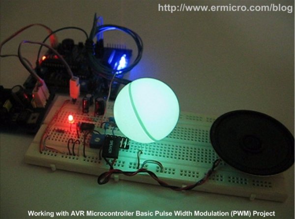
The AVR Microcontroller PWM Peripheral
Most of the microcontroller PWM peripheral depends on the TIMER peripheral to provide the PWM signals frequency. The PWM peripheral will use the TIMER counter register (TCNT) as a digital step-up /down and continuously compare to the pre-determine duty cycle register (OCR – output compare register) value.
When TCNT equal to OCR value the wave generator circuit will set (ON) or reset (OFF) the corresponding microcontroller PWM I/O ports. The following picture show a simplified version of Atmel AVR ATMega168 microcontroller PWM peripheral (please refer to the Atmel ATMega48/88/168/328 datasheet for more information):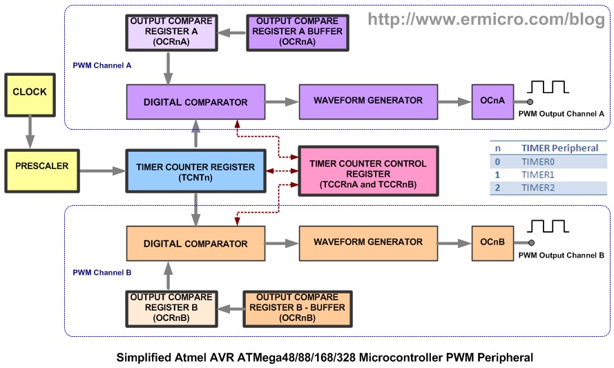
Each of the AVR ATMega168 microcontrollers TIMER has two PWM channels named channel A and channel B, where each channel has its own output compare register (OCR). From the diagram above you could see that both channel share the same TIMER counter register (TCNT), this mean you could only have one PWM frequency for each TIMER (TIMER0, TIMER1, and TIMER2) but you could have different duty cycle on each channel (A and B). The AVR ATMega48/88/168/328 microcontroller provides three PWM modes which are Fast PWM Mode, Phase Correct PWM Mode, and Phase and Frequency Correct Mode. The last mode is only available on TIMER1 (16-bit timer). Ok before we continue let’s list down the hardware and software needed for this tutorial:
For more detail: Working with Atmel AVR Microcontroller Basic Pulse Width Modulation (PWM) Peripheral
About The Author
Ibrar Ayyub
I am an experienced technical writer holding a Master's degree in computer science from BZU Multan, Pakistan University. With a background spanning various industries, particularly in home automation and engineering, I have honed my skills in crafting clear and concise content. Proficient in leveraging infographics and diagrams, I strive to simplify complex concepts for readers. My strength lies in thorough research and presenting information in a structured and logical format.
Follow Us:LinkedinTwitter