Introduction
We designed a system for wirelessly controlling relays and monitoring current. This is used for a home load simulation. By wirelessly turning relays on and off by sending commands from a PC to a microcontroller we can change the total load (current) to our simulated home. For wireless communication, we used XBee Series 2 Zigbee RF modules. One of these modules was connected to a microcontroller and the home load simulation, while another was connected to the PC, which was used for collecting and displaying data as well as for relay monitoring and control.
Rationale and sources of your project idea
This project was proposed by a research/project team here at Cornell working on a so-called Smart Home Energy Monitoring System. Our points of reference within this group are Professor John Belina ([email protected]) and Kamil Bojanczyk ([email protected]).
In the above diagram, the Magic Box essentially exists to route energy between the house, the various energy sources (for example, a solar cell or the electric grid), and an energy storage unit (such as a rechargeable battery). In this project, we will black box this Magic-Box system, and instead focus on another portion of this energy monitoring system, which involves sending data regarding energy usage and various energy loads (by wirelessly controlled relays) to a PC in order to display and monitor energy usage within the home.
Our project focuses on the House to In-Home Display (IHD) part of this system. What our project does is the following:
Simulates a home by using resistors to model various appliances or groups of appliances
Allows a user to wirelessly turn on and off various sets of appliances by controlling relays
Monitors total power consumption and current in this home
Wirelessly transmits the above data to a PC, displaying the data on a graph that shows real-time power consumption in the home (or simulated home)
Our simulated home consists of 7 appliances, each modeled by a resistance (a load). These 7 loads are all in parallel, and are fed voltage from a 5 V DC source (the microcontroller). In a real house, the source voltage would be 120 V AC (in the United States at least). We considered attempting to implement this, but considering the practical dangers of playing around with 120 V AC circuits as well as the fact that a relay control system shouldnt depend on the voltages being fed through the relays led us to decide to stick with 5 V DC circuits for testing and simulation.
Background Theory
What we have built is a simple transmission system based on the Zigbee routing and networking protocol. This protocol and its details are discussed in greater detail in the Standards section (below); in this section, we focus on underlying network theory and the role this theory played in our project.
Data networks (and transmission systems) are typically divided into various layers based on functionality. This is sometimes called a protocol stack (in our case, we are using a Zigbee stack). Essentially, the lower the layer, the closer we are to worrying about actual physical electrons flying around. Conversely, the higher the layer, the less we are worrying about physical constraints and the more abstract the data structures are that we are dealing with and manipulating.
Physical Layer
The physical layer’s job is to move individual digital bits from one place to another. The protocols in this layer depend on the actual physical medium. For example, in a wireless system, the actual physical medium is simply the atmosphere.
Link Layer
A network’s link layer routes a series of bits (sometimes called a datagram) from one node in a network to another. This can happen through a series of intermediate switches (or routers). Protocols at this layer provide more robust and full-featured services than protocols at the physical layer. WiFi is one example of a link-layer protocol.
Network and Transport Layers
Again, since these layers are higher in the model, protocols at this layer typically are more full-featured than protocols at the link or physical layers. Protocols at these layers use the link layer’s routing capabilities to move the aforementioned datagrams between nodes in a network. The Internet Protocol (IP) is probably the most famous network layer protocol, while the Transmission Control Protocol (TCP) and the User Datagram Protocol (UDP) are two examples of well-known and widely-used transport-layer protocols. Certain higher-level functionality is more prevalent in these two layers than in lower levels. For example, flow control controlling the transmission rate between nodes in order to lower congestion on the network (realizing that even just a two-node transmission system can be considered a network) and reliable transmission (ensuring that a packet is actually received) are two features commonly implemented in the network and transport layers.
Session, Presentation, and Application Layers
These layers are essentially the end-result of a networking protocol stack. For example, a web browser resides in the application layer. These layers make use of all of the lower layers to send data between nodes on a network, and then use their own protocols for manipulating that data. A web browser renders HTML but uses lower-level protocols to send HTML between nodes in a network.
Our Project
The part of our project that we implemented basically deals with the network layer and above. The XBee chips (which are discussed in much greater detail later in the report) and firmware allow us to black box the Data Link and Physical layers, and the open source Xbee-API and Xbee-Arduino software packages greatly simplified our work in the network layer. Thus, it was not strictly necessary for us to have a deep understanding of the underlying physical, link, and network layer protocols used, but a brief discussion of this is warranted nonetheless.
The physical layer protocol/standard used in Zigbee systems is IEEE 802.15.4 (http://www.ieee802.org/15/pub/TG4.html). This is a wireless standard that operates, in North America, in the range of 2400-2483.5 MHz or 902-928 MHz. Zigbee, and most importantly our chips, operate in the higher 2.4 GHz range, so that is the range we will briefly discuss here. The data transmission rate is up to 250 kilobits per second.
Logical Structure
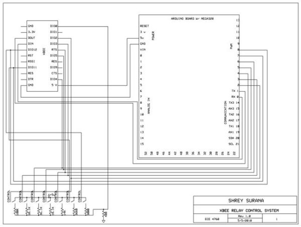
A block diagram of our system is shown below. As you can see there are seven relays which are controlled by the MCU. The MCU gets its command from the Xbee Chip which is wirelessly transmitted from another Xbee chip that is connected to the PC. The user can specify from the PC which relays they want to turn on and off. Also all seven of the relays load goes through a .2 ohm power resistor which goes through an optoisolator to keep it safe from the MCU and finally to the Xbee chip. This gets transmitted back to the PC to be displayed on a graph in a GUI.
Hardware/Software Tradeoffs
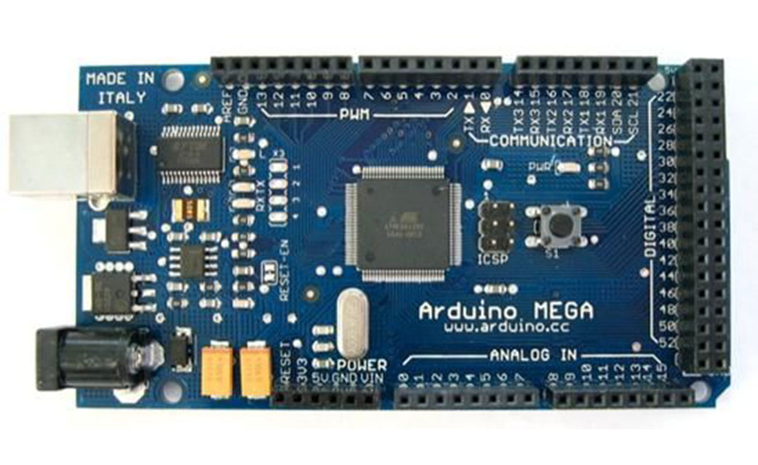
We didnt really have much hardware/software tradeoffs because we didnt have a budget constraint since we were working for a project team. However we did decide to use an Arduino board instead of the STK500 which we were used to. This required less software for us to write. It seemed much less tedious to write certain tasks in Arduino such as turning on an LED. We were interested in expanding our knowledge of other hardware/software that were similar but not exactly the same as what we had learned throughout the semester. Other than that we did not have to do any other sort of tradeoff between hardware and software.
Standards
The most relevant standard for our project is the Zigbee wireless networking standard, which is IEEE 802.15.4. The reason we chose Zigbee over WiFi (802.11) or another RF standard was twofold. First, it consumes a very low amount of power, which could be very useful on the MCU-end of our transmission system (see Tentative Design section). And second, it is (apparently) of much lower complexity than WiFi, making it easier to implement. It has a lower data rate than WiFi (only up to 250 Kbits/second) but is still easily capable of transmitting the relatively low amounts of data that are necessary in this domain. The main feature of this standard is the necessity of achieving technological simplicity, low operation cost, and low manufacturing cost without sacrificing flexibility or generality.
Software Details
Overview
The software portion of this project consists of two main applications: one for an Arduino-based microcontroller unit, and another for the PC. Arduino, as discussed in the hardware section, is an open-source electronics prototyping platform based on Atmel microcontrollers (in our case, an ATMega328) and its own Arduino programming language. This language is very similar to C/C++, and the programming paradigm is almost exactly the same as it is when writing in C for AVR-GCC and Atmel MCUs.
On the PC side, we used Java to interact with an XBee chip connected through either a serial or a USB port (in other words, the XBee is recognized as a serial device on the PC).
Evolution of Software Design
The reason for choosing a Java-Arduino based system is simple: we found a pair of very well-documented open source (GPLv3) projects implementing an API for data transmission using XBee chips and the Zigbee protocol. These projects are:
– XBee-API: This is for the PC side. It is a Java software library with the goal of providing a flexible and simple to use API to interact with XBee radios.
– XBee-Arduino: This is very similar to the XBee-API package (and was written by the same person), but is for Arduino-based micrcontroller platforms rather than PCs.
Parts List:
|
Number |
Item |
Part Number |
Vendor |
Cost |
|
2 |
Xbee 802.15.4 Series 2 Chip Ant |
XB24-BCIT-004-ND |
DigiKey |
$21.00 |
|
1 |
Xbee Explorer Regulated |
WRL-09132 |
Sparkfun |
$9.95 |
|
1 |
Xbee Explorer USB |
WRL-08687 |
Sparkfun |
$24.95 |
|
1 |
Arduino Main Board with Atmel Mega328 |
DEV-00666 |
Sparkfun |
$29.95 |
|
1 |
USB Cable A to B |
CAB-00512 |
Sparkfun |
$3.95 |
|
1 |
USB miniB cable |
CAB-00598 |
Sparkfun |
$3.95 |
|
7 |
Mechanical 5VDC Relays |
Z2320-ND |
DigiKey |
$5.93 |
|
2 |
WhiteBoard |
N/A |
Lab |
$6.00 |
|
1 |
390 Ohm Resistor |
N/A |
Lab |
$0.00 |
|
1 |
18 Ohm Resistor |
N/A |
Lab |
$0.00 |
|
18 |
Various resistors to model load from 330 to 100,000 Ohms |
N/A |
Lab |
$0.00 |
|
|
|
|
Total |
$168.26 |
For more detail: Zigbee Wireless Relay Control and Power Monitoring System Using Atmega644