Last year 2016 I altered my garden and planted some new stock. Half way through the growing season I noticed that the right hand Carnation had grown far more vigorously than its twin only 20” away. The only differences to the plants was that a solar powered battery light had been placed by chance to shine directly down on the right hand plant.
I’m not sure why the three low powered LED’s would have made such a marked difference but I am going to try and see if I can create the same effect in my failing greenhouse.
As I am powering this project with a solar powered 7ah battery I want to make sure that I am not wasting power so I have created three light “zones”.
Sunshine , its pointless using light’s during direct sunshine, lights off.
Night time, I don’t want too attract unwanted two legged visitors so, lights sleeping.
Low light, times of low light dawn till dusk etc, lights on.
Sunshine and Low light are fairly straight forward on/off software controls, but Night time is a little different, I will show why in the software.
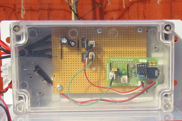
As I require the same sensor to control these zones I have used a Picaxe 8m2 micro controller and 8m2 project board to do the work. The circuits I have made are fairly straightforward and I have included circuit diagrams, I’m not an expert in circuit drawing but I think its all pretty straightforward.
Step 1: Picaxe Circuit
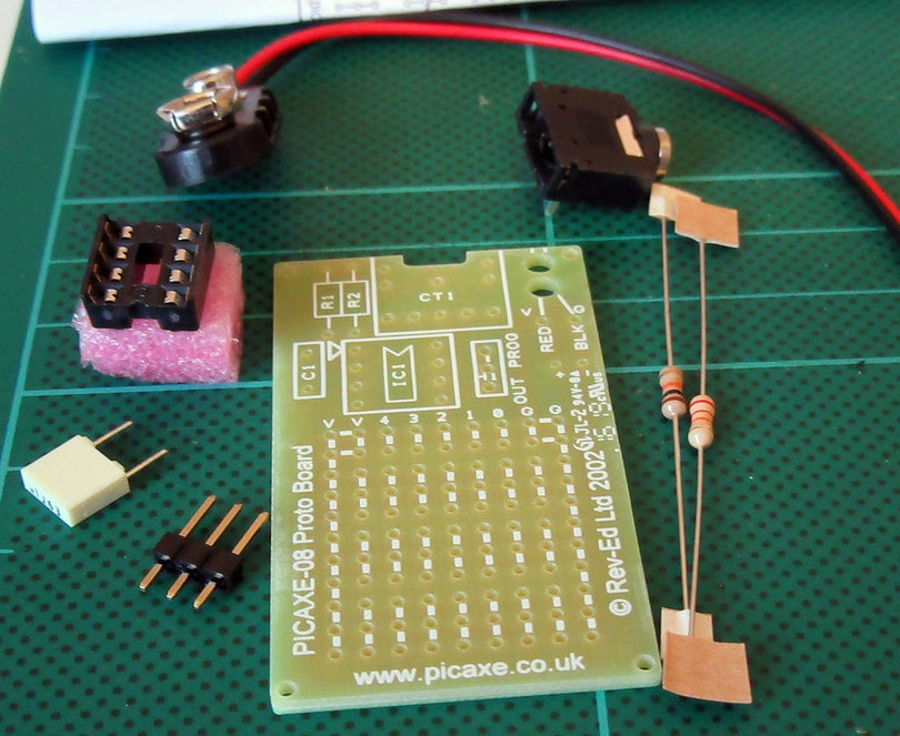
The Picaxe project board kit is reasonably cheap and for simple circuits is adequate. I will describe the circuit by using the pin designations.
CO.0 is the serial output and it joins the 5v and 0v supply at the 3 pin connector. I use this connector to display the sensor value and unit conditions on a LCD unit.
CO.1 is the impulse line that controls the mosfet. It only needs a single line but I’ve used a double connector as it was all I had.
CO.2 is a LED indicator used to indicate that the unit is in test mode.
CO.3 this line is used to set pin 3 high when a jumper is connected across, this puts the software into test mode. The 10k resistor is used to pull down the line when the jumper is removed.
CO.4 a light dependant resistor and the 1k resistor form a voltage divider at pin 4 the pic then converts this analogue voltage to a digital number.
I have used the supplied battery cable so I can use battery power if I remove the Picaxe from the main board but I will be using the regulated 5v from the power circuit board via the 2 pin connector normally.
Step 2: Power
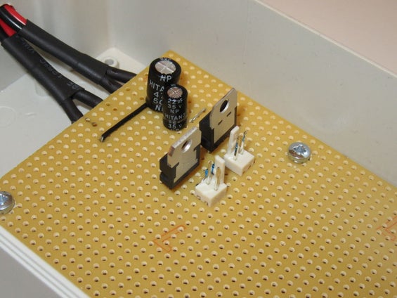
I’ve made a “normal” type of voltage regulator plus Mosfet circuit and all the information is on the diagram.
Pic+ and neg is the power connector for the Picaxe
C1 is the impulse line from CO.1 and the 10k resistor is the pull down for this line, again I had to use a double connector but its a single wire.
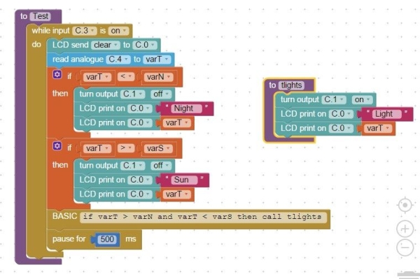
Step 3: Software Main Loop
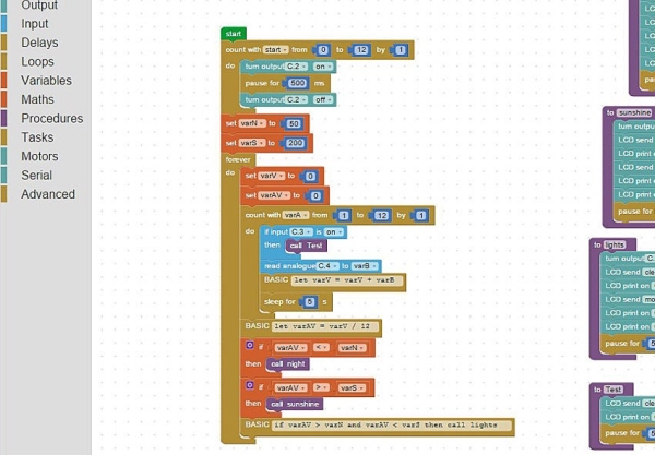
I’ve written the software using Blocky a facility in the Picaxe Editor software plus some basic inserts. The main part is contained in a loop but first every good Picaxe program should start with a blinking LED and that is created with a 12 step for next loop (that sequence is not a part of the main loop).
VarN (night) and varS (sunshine) are then given their set points i.e. an average sensor reading below 50 will call the night procedure.
VarV and varAV are set to zero
A for next 12 step loop is next.
With each step C.3 is checked to see if it set on (on would call the test procedure.)
The analogue value is taken from C.4 and placed as a digital number into varB.
VarB is then added to varV.
The program then sleeps for 10 seconds. A second in this particular Picaxe is actually 2.1 seconds long so sleep 5 = 10 / 2.1 then rounded up.
After the 12 steps and around 120 seconds have passed varV is divided by 12 and the resulting average is placed in varAV.
The average varAV is then compared to 3 statements and the relative procedure is called
Step 4: Software Procedures
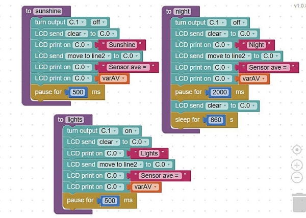
Sunshine and Lights procedures are very similar. These procedures turn C.1 either on or off and print a message on a LCD if fitted then return to the main loop.
Night is also simular to the previous two the main difference being that the program sleeps for 30 minute periods during the night to save power.
Step 5: Test Procedure and Set Up
To get a readout from the unit I use a simple LCD supplied in kit form from the Picaxe Store but to get the initial setting the unit can be connected with the download cable and the analogue sensor facility in the Picaxe Editor will give a real time reading from the sensor.
To get the high and low cut of points (varN and varS) to initially set the unit the jumper is used and C.3 goes high then a note is taken of the sensor value, i.e. when the natural light level has dropped or risen to the point were I want the unit to switch off I take a note of the sensor value from the test screen then update the program with that setting.
During the test procedure shading the LDR or illuminating it will cause the lights to turn on and off so that I can actually see that the unit is working.
Step 6: Complete
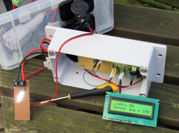
The unit works as planned in the R&D dept and it is now ready for fitting in the greenhouse for its trial run.
I don’t imagine I will get it right first time so I think my Research and Development Dept (my wife calls it the back bedroom) could be busy over the coming weeks.
I also hope that people can understand my steps and diagrams and if not I’m always open to questions .
Source: Picaxe Greenhouse Light Sensor Controller