Summary of 7-Segment Display Interfacing with AVR ATmega16/ATmega32
This article explains 7-segment LED displays, which consist of 7 segments plus a decimal dot for displaying digits and some letters. It covers common anode and cathode types and details their interfacing with ATmega16/32 microcontrollers via direct port control or using a driver IC (SN7446AN). Multiplexing multiple 7-segment displays is also demonstrated using interrupts and timers to improve efficiency and brightness control. Sample code snippets for all methods are provided to showcase real-time display of numbers 0-9 and multi-digit values.
Parts used in the 7-segment Display Project with ATmega16/32:
7-segment LED display (common anode or common cathode)
ATmega16 or ATmega32 microcontroller
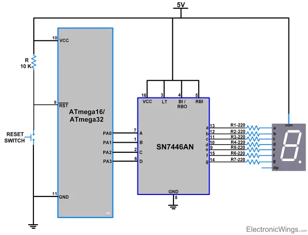
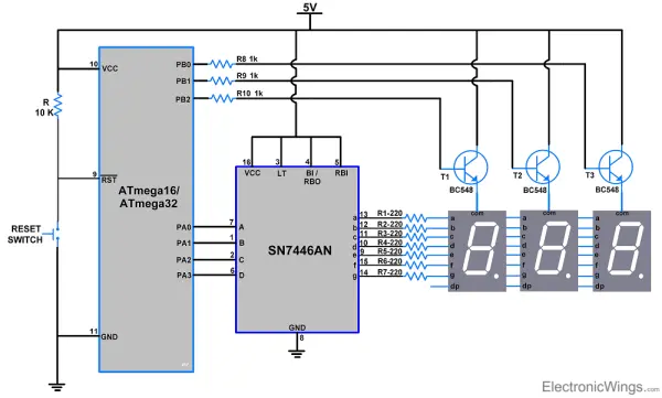
Driver IC SN7446AN (optional, for BCD to 7-segment decoding)
Resistors (for current limiting, not explicitly mentioned but typically required)
Connecting cables/wires
Power supply (5V typical for microcontroller and LEDs)
AVR programming setup (hardware and software tools)
7-segment displays comprise 8 LED elements – 7 linear segments that form numerals, plus a circular dot. Numbers 0-9 and some letters (A, C, D, E, F, H, L, O, P, U) are represented using combinations of the 7 lines. The dot creates decimals.
Each element connects to a dedicated pin, allowing individual control. Pins receive high or low signals to turn elements on/off based on the desired character.
7-segment displays come in common anode or common cathode configurations, impacting signal requirements. With common anode, segments are activated by a low signal. Common cathode uses high signals.
For more details on 7-segment displays, including interfacing and character mapping, please refer to the dedicated topic in the sensors and modules section. Proper understanding of the display type and driving signals is crucial for successful implementation in code.
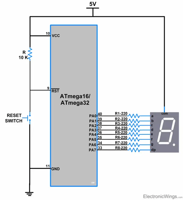
Connection Diagram of 7-segment with ATmega16/32
Interfacing 7-Segment LED Display With AVR ATmega16/ATmega32
7-segment Display Code for ATmega16/32
#define F_CPU 8000000UL
#include <avr/io.h>
#include <util/delay.h>
#define LED_Direction DDRA /* define LED Direction */
#define LED_PORT PORTA /* define LED port */
int main(void)
{
LED_Direction |= 0xff;/* define LED port direction is output */
I am an experienced technical writer holding a Master's degree in computer science from BZU Multan, Pakistan University. With a background spanning various industries, particularly in home automation and engineering, I have honed my skills in crafting clear and concise content. Proficient in leveraging infographics and diagrams, I strive to simplify complex concepts for readers. My strength lies in thorough research and presenting information in a structured and logical format.
This website uses cookies to improve your experience. We'll assume you're ok with this, but you can opt-out if you wish.ACCEPTPrivacy Policy
Manage consent
Privacy Overview
This website uses cookies to improve your experience while you navigate through the website. Out of these, the cookies that are categorized as necessary are stored on your browser as they are essential for the working of basic functionalities of the website. We also use third-party cookies that help us analyze and understand how you use this website. These cookies will be stored in your browser only with your consent. You also have the option to opt-out of these cookies. But opting out of some of these cookies may affect your browsing experience.
Necessary cookies are absolutely essential for the website to function properly. This category only includes cookies that ensures basic functionalities and security features of the website. These cookies do not store any personal information.
Any cookies that may not be particularly necessary for the website to function and is used specifically to collect user personal data via analytics, ads, other embedded contents are termed as non-necessary cookies. It is mandatory to procure user consent prior to running these cookies on your website.