Summary of Flyback Switch Mode Power Supply Circuit
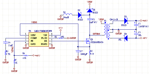
This flyback SMPS design boosts an input voltage of around 20V up to 40V or more by adjusting feedback resistors. It utilizes an off-the-shelf CoilCraft transformer and the LM3479 controller, operating around 500kHz by setting resistor R1 to 39kΩ. A unique feature is powering the regulator at +5V, separate from the coil voltage (VPIN), allowing flexibility in input voltage. The circuit includes a non-dissipative snubber to reduce MOSFET voltage spikes. Customizations can be made using design calculators or by selecting different transformers.
Parts used in the Flyback SMPS:
- CoilCraft transformer
- LM3479 controller IC
- Resistor R1 (39kΩ)
- MOSFET transistor
- Non-dissipative snubber circuit components
- 5V voltage supply for regulator
- Feedback resistors
This is a flyback SMPS that will boost voltage a voltage of around 20V to 40V, or more if you change the feedback resistors. It uses an off the shelf transformer from CoilCraft. The LM3479 is a nice controller because it’s frequency of operation can be set by changing R1. At 39K it runs at about 500KHz.
One innovation of the circuit is that the regulator is driven with +5V, a smaller voltage than VPIN. Separating the regulator voltage supply from the supply driving the coil allows VPIN to be nearly any value. Of course you need to have the 5V generated else where.
The circuit also has a non-dissipative snubber circuit on the drain of the MOSFET, to limit the voltage spikes when the transistor turns off.
See our calculators to make modifications to the feedback circuit, or use a different transformer.
Do you need help with an electronics design? Daycounter provides contract electronics design services. Contact us to give you a quote on your electronics design project.
For more detail: Flyback Switch Mode Power Supply Circuit

