Summary of Faraday For Fun: An Electronic Batteryless Dice using Microcontroller ATTiny13
This project describes building a muscle-powered, battery-less electronic dice using a Faraday voltage generator. The generator consists of a Perspex tube with magnets that induce AC voltage in a coil when shaken. The AC voltage is rectified, filtered, and regulated to power an ATTiny13 microcontroller and seven LEDs arranged like a dice face. The microcontroller detects shaking, generates a random number 1–6 when shaking stops, and outputs that on the LEDs. The system is powered solely by the muscle-driven generator without batteries.
Parts used in the Electronic Batteryless Dice:
- Perspex tube (6-inch length, 15mm outer diameter, 12mm inner diameter)
- Three rare-earth cylindrical magnets (10mm diameter, 10mm length, McMaster #8532K15, amazingmagnets.com #D375D)
- 30 SWG magnet wire (~1500 turns wound on tube groove)
- Rectifier diode bridge
- 4700µF / 25V electrolytic capacitor
- Low Dropout Regulator (LDO) LP-2950 (5V output)
- Zener diode (4.7V)
- Resistor (1.2kΩ)
- 7 high-efficiency 3mm blue LEDs (transparent packaging)
- Microcontroller ATTiny13 (8-pin AVR)
- Shock absorbing pads (e.g., IC packaging foam)
- PCB materials (for end caps sealing the tube)
- Two-part epoxy (for gluing tube ends)

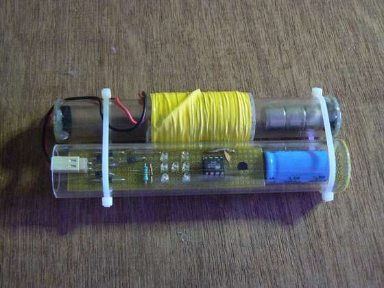
The muscle powered voltage generator is based on Faraday’s law, consisting of a tube with cylindrical magnets. The tube is wound with a coil of magnet wire. As the tube is shaken, the magnets traverse the length of the tube back and forth, thus changing the magnetic flux through the coil and the coil therefore produces an AC voltage. We will come back to this later in the Instructable.
This Instructable shows you how to build an electronic, batterless dice. A photograph of the built unit is seen below.
But first some background —>
Step 1 An Electronic Dice
Step 2 Power Supply for the Dice
If the user desires portability of the dice, then the wall wart transformer should be replaced with a suitable battery, say a 9V battery.
Other options for the battery exist, for example, to be able to operate the dice from a single AA or AAA battery, a normal linear regulator will not work.
To derive +5V for the dice operation, a suitable boost type DC-DC converter must be used. Figure illustrates a +5V power supply suitable for the dice operation from a wall 9V battery and the other figure shows the schematic for a +5V power supply from a 1.5V AA or AAA type battery using a TPS61070 boost DC-DC converter.
Step 3 Free Power: Use your Muscles..
Such a tube is available from McMaster (mcmaster.com), part number: 8532K15. Magnets can be bought from amazingmagnets.com. Part # D375D.
Step 4 Voltage Generator Performance
Step 5 Dice Schematic
I used 7 high efficiency 3-mm blue LEDs in transparent packaging, arranged in the dice form. The LEDs are controlled by an 8-pin AVR microcontroller, the ATTiny13. The voltage output from the faraday generator is a pulsed output. This pulsed output is conditioned with the help of a resistor (1.2KOhm) and a Zener diode (4.7V). The conditioned voltage pulses are sensed by the microcontroller to determine if the tube is being shaken. As long as the tube is shaken, the microcontroller waits. Once the user stops shaking the tube, the microcontroller generates a random number, using an internal 8-bit timer operating in free running mode and outputs the random number between 1 and 6, on the output LEDs. The microcontroller then again waits for the user to shake the tube again. Once the LEDs display a random number, the available charge on the capacitor is sufficient to light the LEDs for an average time of about 10 seconds. To get a new random number, the user must shake the tube a few times again.
Step 6 Programming the Microcontroller
The Tiny13 microcontroller operates with an internal RC oscillator programmed to generate128KHz clock signal. This is the lowest clock signal that the Tiny13 can generate internally and is chosen to minimize the current consumed by the microcontroller.
The controller is programmed in C using the AVRGCC compiler and the flow chart is shown here.
The fuse bits for the controller are also shown here.
I used STK500 to program my Tiny, but you can refer to this Instructable if you prefer an AVR Dragon programmer: http://www.instructables.com/id/Help%3a-An-Absolute-Beginner_s-Guide-to-8-Bit-AVR-Pr/
For more Detail: Faraday For Fun: An Electronic Batteryless Dice using Microcontroller ATTiny13
