Motivation
We design a smart home control system which allow people control their home devices by voice command at home. This is a wireless, voice control system. People could control almost all the facilities at home including lights, fans or even back ground music. Right now, the basic function of lights control, fan control and music control have all been implemented. Except for basic turning on and off of fasilities at home, we also realize the function of fixed-time control, and error detection when some device is broken. The system is quick enough for respond all the commands.
Our smart home system is a simulation product for the future life. The purpose of it is to make people’s lives more convenient. To replace turn on or turn off on switches by hand for current product, our system is controlled by voice. That should be a trend for the future 10 years which we believe that it is coming to real product soon. How to make people’s life more convenient, more comfortable, more safe and how to save more energy will be the series of questions we will care, discuss and design in our project. Just imagining, after you cook a big pot soup and want to leave the kitchen, you don’t have more hands to turn off the kitchen’s light. If our project becomes a mature product, you can set up our system in the home, you can turn off the lights by voice when you hold a pot soup at the same time. When you read the book in bed at night, you are not sure when you will sleep, you can tell the system when you want the light turn off, the timer in the system will help count the time and turn off the lights with the time you have set.
Early Work
Why we choose wireless signal transmission?
When someone gets home and wants to enable light, fan, music at home, he may use his voice to control his household appliance. However, the transmission distance of the voice is short and it is even hard to recognize what you said when there is some noise mixed with the signal. Sometimes the voice recognition chip will send out wrong instructions because of the noise outside. So we decide to place a central control unit in the center of the room and send digital signal wirelessly to where other microcontroller is. Once the receiver gets the signal, it will operate on/off/dimmer function which has been programmed in it previously. As xbee could transmit at most 1000 meters, this method avoids the distance problem and signal interference problem.
Why we choose xbee?
XBEE promises many advantages over existing remote control solutions, including richer communication and increased reliability, enhanced features and flexibility, interoperability, and no line-of-sight barrier. In our project we use XBEE for point to point communication. It is efficient and enough to be used in household. The transmission of signal won’t be blocked in a long distance and even by a wall. Due to this spec of the xbees, we may put the center voice recognition microcontroller in the center of one household so that it could communicate any other microcontroller (which has xbee receiver with it) and enable different functions by sending out different instructions. Here, I use different characters, like “a”,”b”,”c” etc to represent controls on fan, lounge room LED and bedroom LED.
X-CTU is the program provided by digi to initialize and test with xbee communications. We change the baud rate to 9600, set the same pin number for two xbees through the program so that it is ensures there will be no other xbee or RF devices interfering the wireless communication between two our two xbees.
High Level Design
Rationale and Sources
Many companies on the school career fair showed their products for students. Lutron, a famous lighting control company, focus on the light system for house, company and some other building. They showed us their high-level LED products, with the basic entire control system costs around $3000. We got interested in their product and also figuring out a more convinient way to control and save energy.
After discussing, we consider it could better if we implement the wireless, voice control system in the household. The basic idea of our project is when people stay in the room and within a distance of the device they wants to control, they could control the house electrical devices by voice instructions. Under most of the circumstances, this system will bring more convenience in people’s lives.
Hardware Design
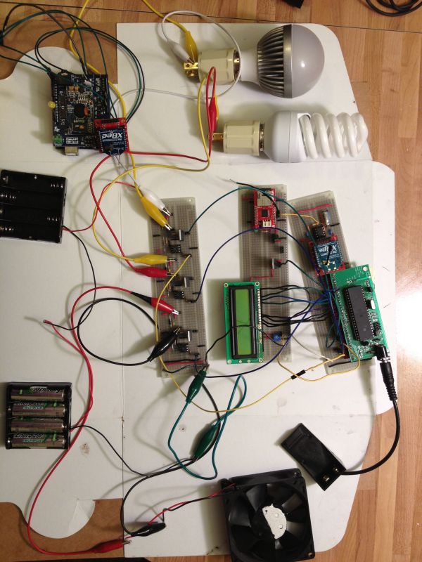
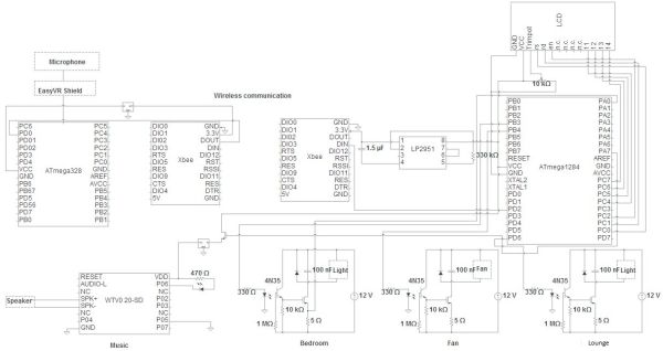
These are the overview of our project schematics and physical map. We solder all of them in three solder boards. The microphone, EasyVR Shield and transmitter Xbee are connected on the ATmega328 chip and no need to solder. ATmega1284 connect to LCD and provide the voltage to the receiver Xbee. We pass the Vcc in a voltage regulator to get the 3.3V to the Xbee. On the other hand, there are three pins provide the PWM waves to the three different home devices. There is one pin is used to connect the gate of NMOS which is let the VCC flow in to the NMOS and into the voltage regulator to get the 3.3V output to the music player chip.
In this part, there are three part, EasyVR Shield which has the microphone, the ATmega328 and the transmitted Xbee. With the ready-made board we can put the EasyVR chip on the ATmega328 direct. We input the 3.3V from the ATmega328 to Xbee and connected the Xbee and ATmega328’s ground. In order to transmit the signal from Xbee we connected Xbee DOUT pin to ATmega328 (PCINT16/RXD) PD0 pin.
We soldered the MCU board by ourselves and we followed the lab1’s lecture to initial the CPU. And then we used it to provide 5V output for all the other chips and connect it with the LCD which follows the lab1 lecture. After check the data sheet of Xbee we connect the DIN with ATmega1284’s PD2. There is a little different between ATmega328 and ATmega1284 at the power output. There is no 3.3V voltage output at ATmega1284. So we use the voltage regulator LP2951 to drop the 5V output to 3.3V. Set up the circuit of LP2951 with the datasheet, we could get the stable 3.3VV output.
Part3-LCD and Music Player
For this board, we set up the circuits of LCD and the music player chip. The music chip is named WTV020-SD module. There are different modes in this module. The MP3 mode, Key mode, Key mode, Loop play mode and two line serial mode. Because we only play the background music, so there is only one music in it. We pick up the loop play mode to play the music. Here is the detailed schematics of WTV020-SD which come from the datasheet.
When we try to use one ATmega1284 pin to enable the chip and provide 5V input into the voltage regulator. But there is a problem here, the current is very low and we can’t let the music player chip work. So we put a NMOS here and let the pin voltage to connect the gate and let the VCC to be the power supply to pass into the voltage regulator to get the 3.3V output. In the way, we could use the program the control the only one pin voltage to get the music player work.
For more detail: Wireless, voice-controllable, household system Using Atmega644