Summary of USB PORT RELAY CONTROL WITH ATMEL ATMEGA8
Summary: A USB-controlled 6-relay board uses an Atmel ATmega8 AVR to emulate a USB-to-RS232 interface, allowing relay control from a PC or web application. The board supports cascading via SPI, includes four optocoupled inputs for isolated monitoring, and handles loads up to 250 VAC/8 A (relay-dependent). Power regulation accepts 9–12 VAC. Firmware and PCB schematics are provided.
Parts used in the USB Port Relay Control with Atmel Atmega8:
- Atmel ATmega8 microcontroller
- USB interface components (USB connector and supporting circuitry)
- Relays (6 units, rated up to 250 VAC, 8 A depending on relay)
- Optocouplers (4 for isolated inputs)
- SPI connector
- RS232 connection circuitry
- Power regulation circuit for 9–12 VAC input
- PCB (schematic and board)
- Support passive components (resistors, capacitors, diodes)
- Driver/firmware from Objective Development (USB driver in AVR firmware)
6 relay control units can be made via the usb port usb drive computer program code and schema files are pcb circuit to regulate the supply 9-12 volt ac section there on the SPI… Electronics Projects, USB Port Relay Control with Atmel Atmega8 “atmega8 projects, avr project, microcontroller projects, “
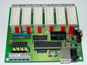
6 relay control units can be made via the usb port usb drive computer program code and schema files are pcb circuit to regulate the supply 9-12 volt ac section there on the SPI and RS232 connections
In fact, with the computer relay to control a simple inexpensive circuit there, but (the PC and the Device Control) these circuits turned the computer port to question his instantaneous even in the relays pull leaves microcontroller used in the system prevent this problem can only be undertaken
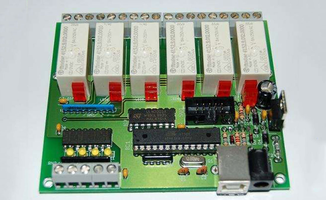
The relays switch max. 250V AC and have a switching current of 8A (depending on the relay used). In addition, can also use 4 inputs, which are isolated by optocouplers, are queried and monitored. The AVR simulates a USB RS 232 interface and so you can relay card can be easily addressed without problems via a terminal program or other software. The USB driver in the AVR firmware comes from the company objective development 6 Channel USB relay card to switch from various appliances, lamps or motors by a computer program via the USB interfaceThis can then using a web application even over the Internet. About the SPI connector would even be possible to relay card with other relay cards to cascade. The relay switch max. 250V AC and have a switching current of 8A (depending on set relay). Also you can also 4 inputs, the optocoupler are separated, queried and monitored. The AVR simulates a USB interface RS 232 thus can relay this card without problems on a terminal program or other software to be easy.
Source: https://320volt.com/en/atmel-atmega8-ile-usb-portundan-role-kart-kontrolu/ USB Relay Control schematic pcb Atmega8 source code files alternative link:usb-port-relay-control-with-atmel-atmega8.rar alternative link2
- What microcontroller is used in the project?
The project uses an Atmel ATmega8 microcontroller. - How many relays does the board provide?
The board provides six relays for switching external loads. - What is the maximum switching voltage and current for the relays?
The relays can switch up to 250 VAC and a switching current of 8 A depending on the relay used. - Can this relay card be controlled via USB from a PC?
Yes, the AVR simulates a USB RS232 interface so the card can be addressed from a terminal program or other software via USB. - Does the board provide isolated inputs?
Yes, there are four inputs isolated by optocouplers for querying and monitoring. - What power supply does the PCB require?
The PCB includes a regulation circuit and accepts a 9–12 VAC supply section. - Is it possible to cascade multiple relay cards?
Yes, cascading is possible via the SPI connector. - Can the relay card be controlled over the Internet?
Yes, the article states it can be controlled using a web application to operate over the Internet. - Where does the USB driver in the AVR firmware originate?
The USB driver in the AVR firmware comes from Objective Development, according to the article.