Summary of Innovative Applications with the Atmel Mega644 Prototype Board
This article details a prototype board for Atmel Mega644 or Mega32 MCUs, featuring power supplies, crystal clocks, bypass capacitors, and headers for programming and serial communication. It includes construction steps for Version 12, emphasizing component ordering and testing. The design supports breadboard attachment and offers all port pins via vias.
Parts used in the Atmel Mega644 Prototype Board:
- Atmel Mega644 or Mega32 MCU (PDIP)
- Power supply components
- Crystal clock (16 MHz or 20 MHz)
- Bypass capacitors
- Six-pin header for flash memory programming
- Vias spaced at 0.1-inch intervals
- 34-connection SIP header plug
- Four-pin header for serial or USB board
- Regulator
- Power switch
- Power plug
- Diode
- MCU socket
- Reset button (optional)
- LED and jumper for debugging (optional)
Introduction
This document outlines a prototype board designed for use with the Atmel Mega644 or Mega32 (PDIP) MCU. The board incorporates essential components such as a power supply, crystal clock, and bypass capacitors. Additionally, it features a six-pin header for flash memory programming from devices like STK500 or AVRISPmkII. All port pins are accessible via a single row of vias spaced at 0.1-inch intervals. A 34-connection, SIP header plug facilitates attachment to other boards or solderless breadboards. Notably, all 32 port pins, along with Vcc and ground, are readily available. Furthermore, a separate interface is provided for serial communication.
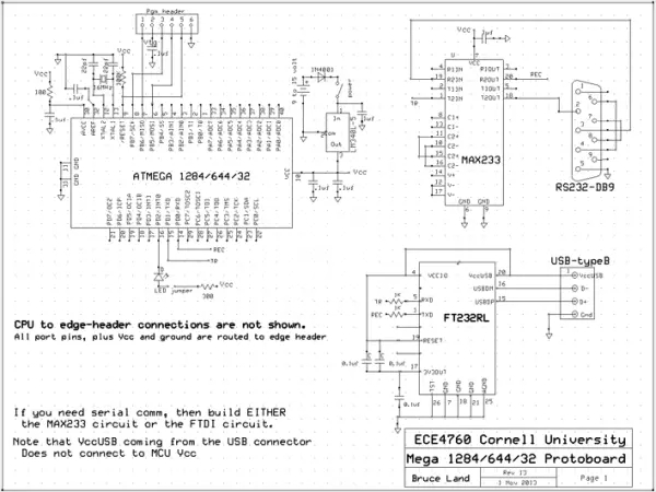
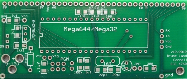
Board Version 12 for 2012
The board layout for version 12 is detailed below. Please note that the design for the subsequent revision (v13-2013) includes main, USB, and serial boards. Express PCB design files are provided for modification or direct ordering from Express PCB.

Main Board
The main board, depicted above, incorporates a four-pin header matching either the serial or USB board. Notable changes from the previous model include the elimination of header pins for Aref and Vcc USB, along with solder pad removal for the TSSOP USB chip.
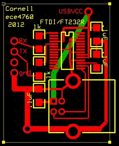
USB and Serial Boards
The USB and serial boards are designed for applications requiring serial communication. It’s essential to construct only one of these boards as per your specific needs. Instructions for building both boards are provided below.
Version 12 Construction Suggestions
Before commencing construction, it’s recommended to study the provided photos. Thinner components should be mounted first to avoid interference with soldering flat components. Follow these steps for efficient construction:
– Solder all capacitors and resistors onto the board.
– Add headers for TX, RX, LED, Vcc-Vtg, and programming.
– Incorporate the regulator, power switch, power plug, and diode.
– Test the power supply to ensure Vcc is within the specified range.
– Install the MCU socket and the 16 MHz (or 20 MHz) crystal.
– Optionally, add a reset button for additional functionality.
– Consider adding an LED and jumper for debugging purposes.
For detailed programming instructions and guidelines for flashing the microcontroller, refer to the provided documentation.
Useful Parts
A comprehensive list of useful parts, along with their corresponding Digikey part numbers, is provided for reference. These parts are essential for constructing and enhancing the functionality of the prototype board.
Conclusion
The prototype board for Atmel Mega644 offers a versatile platform for developing and testing MCU-based projects. With its integrated components and flexible design, it serves as a valuable tool for electronics enthusiasts and professionals alike. Through careful construction and adherence to provided guidelines, users can harness the full potential of this board for various applications.
Follow this link for complete project: Innovative Applications with the Atmel Mega644 Prototype Board
- What microcontrollers does this prototype board support?
The board is designed for use with the Atmel Mega644 or Mega32 PDIP MCU. - How can I program the flash memory on this board?
A six-pin header is provided for flash memory programming using devices like STK500 or AVRISPmkII. - Can I access all port pins on the board?
Yes, all 32 port pins along with Vcc and ground are accessible via a single row of vias spaced at 0.1-inch intervals. - What is the best way to mount components during construction?
Thinner components should be mounted first to avoid interference with soldering flat components. - Does the board include both USB and serial boards?
No, you must construct only one of these boards depending on your specific application needs. - How do I verify the power supply before proceeding?
You should test the power supply to ensure Vcc is within the specified range after installing the regulator and diode. - What optional features can be added for debugging?
An LED and a jumper can be added for debugging purposes, along with an optional reset button. - Where can I find the design files for modification?
Express PCB design files are provided for modification or direct ordering from Express PCB.