Keep an eye on your beloved bbies and play music or tell ’em to be quiet while you are away! This tutorial will show how to use a Raspberry Pi computer to monitor the volume of sound in your home (via the Cloud) to see if and when your pet is upset.
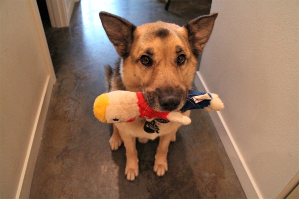
Drum roll… the most fun part: If it gets too loud (like Fido is barking or making some other raucous), we’ll you can tell them to be quiet or play music!
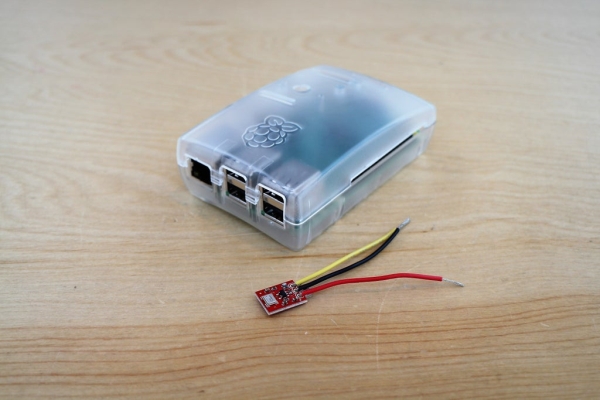
Along with the Pi (and speakers), we’ll use the SparkFun MEMS microphone breakout board to measure volume levels and trigger the audio player. Data is uploaded to the CloudMQTT service using the MQTT communication protocol.
Total Read Time: ~ 8 min
Total Build Time: 60 min (less w/ experienced)
A huge THANK YOU to SparkFun for supporting this project! Check out the tutorial here.
Step 1: Suggested Reading
To build this project, you’ll need a fully configured, WiFi-connected Raspberry Pi 3 computer with Raspbian OS. It’s also helpful to know some Python programming as well as the following things: (1) how to use and control the Raspberry Pi GPIO pins; (2) MQTT communication; and (3) analog sensors. If any of this is unfamiliar, or if you’re just curious (be curious!), check out the tutorials below!
Raspberry Pi 3
MQTT Communication Protocol
MQTT (Message Query Telemetry Transport) is a popular IoT communication protocol. We’ll use the Paho Client Python library and an MQTT service called CloudMQTT. Here’s more about MQTT and how to use it:
- Exploring Communication Protocols for IoT
- Getting Started with CloudMQTT
- Overview of Eclipse Paho MQTT Python client library
MEMS Microphone Breakout Board
The MEMS microphone is an analog microphone, so we’ll need an Analog-to-Digital converter (“ADC”) to read in the analog signal with the Raspberry Pi digital GPIO pins.
- Getting started with the SparkFun MEMS Microphone Breakout Board
- MEMS Microphone Datasheet
- MCP3002 ADC Datasheet
Step 2: Materials
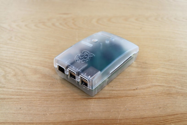
We’ll also need the following peripherals:Raspberry Pi 3 Case; SD Card (minimum 8 GB); Raspberry Pi 3 GPIO cable; MicroUSB power cable; HDMI cable and HDMI-compatible monitor; USB keyboard; USB mouse; speakers with 1/8″ headphone port.
– SparkFun MEMS Mic Breakout Board
– MCP3002 (Analog-to-Digital Converter)
– Breadboard & M-to-M Breadboard Jumper Wires
Step 3: Configure the Raspberry Pi
Step 1: Check & Install Updates
Checking for and installing updates is always a good way to start. Run the following commands in the terminal window:
sudo apt-get update
sudo apt-get upgrade
sudo reboot
Step 2: Set up SPI Interface for MEMS Microphone + MCP3002
To use the SPI (Serial Port Interface) to read in the MEMS Microphone via the MCP3002, we’ll need the Python Dev Package:
sudo apt-get install python-dev
We’ll also need the SPI Interface (may want to create a subfolder to save this in):
git clone git://github.com/doceme/py-spidev
sudo python setup.py install
Here’s the SPI-Dev Documentation if you run into any issues.
Step 3: Playing Sounds with OMXPlayer
The OMXPlayer is an audio and video player pre-loaded on Raspbian OS. It works with most sound file types, including: .wav, .mp3, and .m4a. This is what we’ll use to play back sounds when Fido gets too loud. The Python library to control the OMXPlayer is included in Raspbian (woo!).
To test the OMXPlayer from the terminal, type the following:
omxplayer /home/.../SongFilePath/SongFileName.mp3
If that doesn’t work, try forcing it over the local audio-out device:
omxplayer -o local /home/.../SongFilePath/SongFileName.mp3
Step 4: Configure CloudMQTT Server
Now we set up an MQTT server! To do this using CloudMQTT, do the following:
- Set up a CloudMQTT account (the “Cute Cat” plan is free).
- Create a new MyCloud instance.
- In the Console, create a new ACL rule.
- You can monitor published messages in the “Websocket” UI.
Finally, install the MQTT Paho Client Python library:
pip install paho-mqtt
Step 4: Build It! Hardware
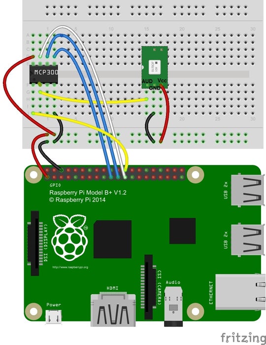
Pinout diagrams for the Raspberry Pi and the MCP3002 are in the photos above.
1. Insert MCP3002 pins into breadboard (see pinout diagram above)
The MCP3002 uses 4 SPI pins for communication: Serial Clock (“SCL”), Master Input Slave Output (“MISO”), Master Output Slave Input (“MOSI”), and Chip Select (“CS”). These pins correspond to Raspberry Pi GPIO pin 11 (SCLK), GPIO pin 9 (MISO), GPIO Pin 10 (MOSI), and GPIO Pin 8 (CE0).
Make the following connections with MCP3002 pins:
- Connect Pin 1 to Raspberry Pi GPIO Pin 8 (CE0)
- Connect Pin 2 to the analog output of the MEMS Microphone breakout board
- Connect Pin 4 to GND
- Connect Pin 5 to Raspberry Pi GPIO Pin 10 (MOSI)
- Connect Pin 6 to Raspberry Pi GPIO pin 9 (MISO)
- Connect Pin 7 to Raspberry Pi GPIO Pin 11 (SCLK)
- Connect Pin 8 to Raspberry Pi 3.3V out
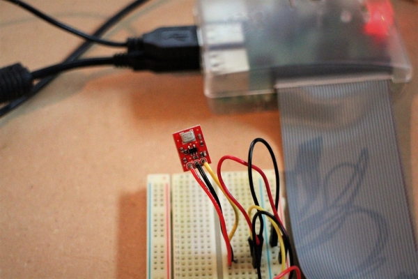
2. Solder wires to the MEMS Microphone breakout board. Connect to MCP3002 and Raspberry Pi.
- Connect Vcc to Raspberry Pi 3.3V.
- Connect GND to Raspberry Pi GND
- Connect AUD to MCP3002 Pin 2
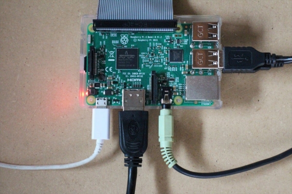
3. Plug in all the cables for the Raspberry Pi and turn everything on.
Step 5: Build It! Software
Our goal with the Bark Back is twofold: trigger a playback sound when the dog barks, and send the data to a server where we can check it.
Here’s the open-source Python program for this project.Feel free to (and please do) adjust and modify the code.
To get the program up and running, you need to fill in two things:
– songList: Write in the file path and file name for each of the songs you want to play.
– creds: Input your CloudMQTT information in this dictionary.
Step 1: Read in the SparkFun MEMS Microphone breakout board.
Read in the ADC value (between 0 and 1023) from the MEMS Microphone breakout board (via the MCP3002) using the SPI library and calculate the signal peak-to-peak amplitude.
Map the signal peak-to-peak amplitude to a Volume Unit. The current code maps the ADC range between 0 and 700 (based on quick experimentation) to a Volume Unit between 0 and 10. To adjust the sensitivity of the microphone, adjust the ADC input range.
For a thorough overview of the MEMS mic, check out this tutorial.
Step 2: Trigger audio player.
First we’ll need songs to play! You can quickly record sounds in GarageBand (or on your smartphone) and send ’em to the Raspberry Pi. In Python, use the subprocess library to call the omxplayer.
In the code, input the file path of the songs you want to play back in the *songList* variable (line 26). The current volume threshold is set to 7 in the main function.
Step 3: Send data to CloudMQTT Server
Use the Paho Client Python library to communicate with the CloudMQTT servers. To broadly summarize: Set up a Client server; define communication protocols; connect with our credentials (aka creds); and subscribe and publish our data. Most of this is done in the main function (lines 129 – 149, and lines 169 – 174).
To check on received data, go to the “Websocket UI” tab in the CloudMQTT console.
Step 6: Test & Install!
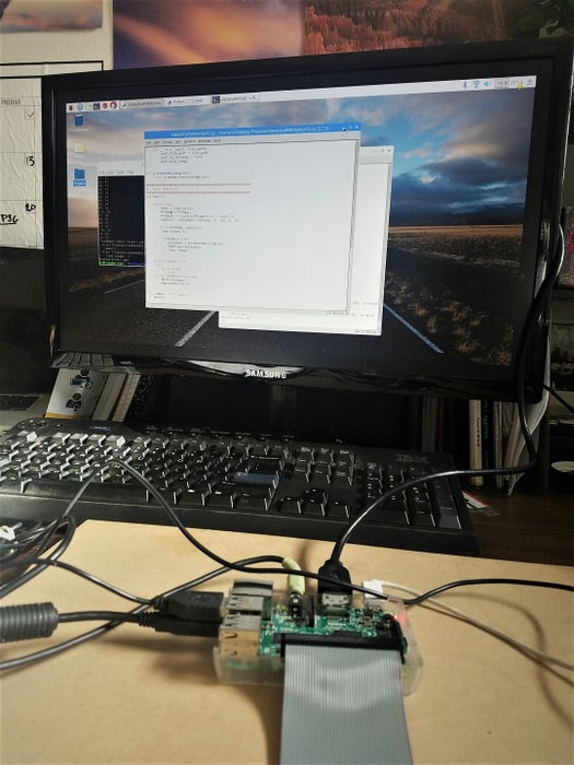
Run the BarkBack.py program in Terminal or in the Python IDE (you can also use SSH to run the program after you’ve already left).
Check that you are getting volume levels in your Websocket UI tab.
Test the system by triggering the mic (clap, yell, bark, etc.) to be sure that the speakers play through all of the sounds.
Once everything is up and running, it’s recommended to solder the components to a PCB (Printed Circuit Board) if you intend to install the system for more than just a few days.
Source: IoT Pet Monitor!