Summary of Keypad Interface With 8051 and Displaying Keypad Numbers in 7 Segment
This tutorial explains how to interface a keypad with an 8051 microcontroller and display the pressed keypad numbers on a seven-segment display. It covers the software required such as Keil uVision for coding, Proteus for simulation, and Flash Magic for hardware programming. The project uses a 4x3 keypad matrix and a common anode seven-segment display with an 8051 development board. Resources include a circuit diagram, source code on GitHub, and a demonstration video.
Parts used in the Keypad Interface With 8051 and Displaying Keypad Numbers in 7 Segment:
- 8051 Development Board
- Common Anode Seven Segment Display
- 4x3 Keypad Matrix
- USB to UART Converter (9 Pin D type male Connector)
- Jumper Wires
In this tutorial I’m going to tell you about how we can interface keypad with 8051 and displaying keypad numbers in 7 segment display
Step 1: Software Used
As we are showing proteus simulation so FOR CODING AND SIMULATION YOU REQUIRED:
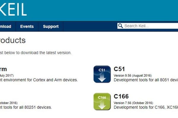
1 Keil uvision: Their are lots of product from keil. so you will be required c51 compiler. You can download that software from here
2 Proteus Software for simulation: This is the software to show simulation. You will get lot of information to download this software.
If you are doing it in hardware then you would require one software that is flash magic to upload the code in your hardware. Remember flash magic is developed by nxp. So you can not upload all 8051 family microcontroler through this software. So Philips based controller only you can upload.
Step 2: Components Used:
Here in our demo video we are using proteus simulation but definetly if you are doing it in your hardware you will be required these components for this project:
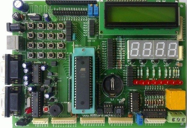
8051 Development board: So if you have this board it will be better so that you can easily upload the code by yourself.
Seven Segment Display: In this project we are using one Common Anode Display.
4*3 Keypad Matrix: Herewe are using 4*3 keypad matrix. So you can use 4*3 matrix or any other matrix like 4*4, no issue. For that a little more step we need to add in our code
USB to UART converter: This is 9 Pin D type male Connector For RS232 O/p Jumper Wires
Some Jumper Wires
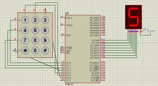
Step 3: Circuit Diagram:

Step 4: Code and Video
The whole Project Description is given in above video
You can get the source code from our GitHub Link
If you have any doubt regarding this project feel free to comment us below. And if you want to learn more about embedded system you can visit our youtube channel
Please visit and like our Facebook Page for frequent updates.
Thanks & Regards,
Embedotronics Technologies
Source: Keypad Interface With 8051 and Displaying Keypad Numbers in 7 Segment