Summary of NOKIA5110 LCD LOGIC ANALYZER CIRCUIT ATMEGA8
This project describes a Logic Analyzer built using the ATmega8 microcontroller, designed to interface with a Nokia 5110 LCD display. Developed with AVR Studio software, the device captures signal frequencies up to 400 kHz with a maximum input and operating voltage of 5V. It supports battery operation using four 1.2V rechargeable batteries. The analyzer can measure both high-speed signals (3.7 ms) and low-speed signals (36 seconds). Complete source code, schematics, PCB layouts, and configuration files are available for this AVR-based logic analyzer.
Parts used in the Logic Analyzer with Nokia 5110 LCD Display Project:
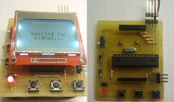
- ATmega8 microcontroller
- Nokia 5110 LCD display
- 4 x 1.2V rechargeable batteries (for 5V operation)
- Power supply (battery or regulated 5V source)
- AVR Studio software (for programming and configuration)
- PCB (custom designed for the circuit)
Built on the atmega 8 microcontroller Logic Analyzer circuit for nokia 5110 display lcd display kullanılanılıyor crafted with AVRstudio Software four. source software insurance settings schema, pcb, etc. files. Frequency capture 400 kHz, Max… Electronics Projects, Nokia5110 LCD Logic Analyzer circuit ATmega8 “atmega8 projects, avr project, microcontroller projects, “
Built on the atmega 8 microcontroller Logic Analyzer circuit for nokia 5110 display lcd display kullanılanılıyor crafted with AVRstudio Software four. source software insurance settings schema, pcb, etc. files.
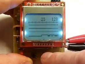
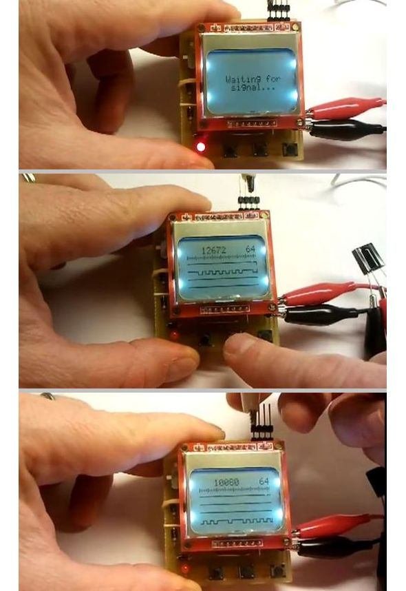
Frequency capture 400 kHz, Max input voltage 5v dc, operating voltage 5v (4 x 1.2 v rechargeable battery) to capture high speed signals, signal 3.7 ms, low-speed signals 36s
Note: If you are going to be the battery voltage of 1.2 v power supply for battery 1.5 v alkaline batteries if you use in total 6v voltage and atmega8.
Source: serasidis.gr/circuits/mini_logic_analyzer/miniLogicAnalyzer.htm alternative nokia5110-lcd-logic-analyzer-circuit-atmega8.rar alternative link3