Summary of REMOTE-CONTROLLED DIGITAL TIMER CIRCUIT WITH ATMEL ATTINY2313
This project features a remote-controlled digital timer based on the Atmel ATtiny2313 microcontroller. It uses the RC5 protocol to manage forward and reverse timer control via a remote. Timer settings are displayed on an LED display, and the microcontroller controls a relay through pin PD5. The project includes source codes, PCB layouts, diagrams, and component dimensions for building the circuit.
Parts used in the Remote-Controlled Digital Timer Circuit with Atmel ATtiny2313:
- Atmel ATtiny2313 microcontroller
- LED display
- Relay
- Remote control (RC5 protocol compatible)
- Supporting passive components (resistors, capacitors, etc.)
- PCB for circuit assembly
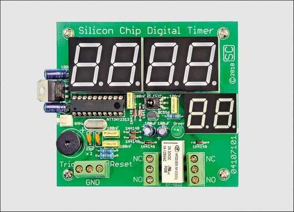
Based on Atmel ATtiny2313 microcontroller circuit with the remote control forward / reverse control can be done over time led display are viewing. ATtiny2313 by the time specified number 9 which is connected to…Electronics Projects, Remote-Controlled Digital Timer Circuit with Atmel ATtiny2313 “avr project, microcontroller projects, “
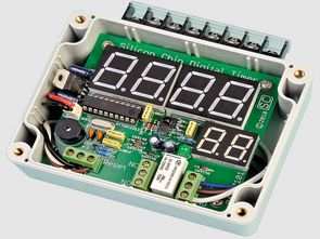
Based on Atmel ATtiny2313 microcontroller circuit with the remote control forward / reverse control can be done over time led display are viewing. ATtiny2313 by the time specified number 9 which is connected to pin PD5 trying to relay is happening.
RC5 protocol used for remote control of the circuit can be used any source control settings sigot c hex codes, pcb, diagrams, dimensions, etc. dry. There are files.
DIGITAL TIMER CIRCUIT REMOTE CONTROL
Source: https://320volt.com/en/attiny2313-ile-uzaktan-kumandali-dijital-zamanlayici-devresi/ Atmel ATtiny2313 Digital Timer Circuit Alternative link: remote-controlled-digital-timer-circuit-with-atmel-attiny2313.rar