Introduction
We have designed and constructed an autonomous photo capturing system that detects and tracks faces, centers subjects in the frame, and takes pictures. Since the most straightforward application for our robot is to take pictures of oneself without the aid of others, we have fittingly dubbed our system the “Selfiebot”. When operating our device, the user may specify a variety of preferences through its simple GUI, including contrast, brightness, centering options, the number of people to capture, and the number of pictures to take.
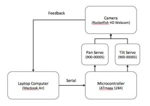
Our system processes images taken from a webcam on a laptop computer, using facial detection to track subjects, and forms movement commands to center the subjects based on face positions. The laptop sends the commands to an ATmega1284 microcontroller via serial communication, and the microcontroller controls the movement of two servos on the robot. These two servos correspond with panning and tilting actions, allowing for two dimensional movement of the camera. Feedback from the camera is used to continuously update movement.
2.1 Motivation and rationale:
Millennials are biggest fans of taking lots of photos, especially of themselves and their friends. Mostly themselves. In this day and age people are always focused on getting that perfect selfie; it is the age of the selfie. After all, we can’t always rely on other people to take our pictures, because either there aren’t always other people there, or their photography skills are just not up to par. However, it’s not always that easy. Sometimes their arm isn’t long enough to fit everything in the picture. Sometimes their aim isn’t good enough. And there is also a social stigma surrounding taking selfies. People judge each other when they see that they are taking selfies, because it somehow suggests vanity or lack of friends, even though everyone does it. When a selfie just isn’t possible, we must, in desperation, resort to reaching out to complete strangers, who may or not be good photographers, for help in taking a picture of us and our friends.
Now imagine that you have a personal picture taking robot that you can carry with you. With a simple command, you can get in that perfect pose and the robot will find your face and take a beautiful, customized photo for you. With this selfie robot, you no longer have to worry about begging strangers to stop and take a picture for you. Also you don’t have to annoy your friends and keep asking them to take a picture. You don’t even have to take the picture yourself and struggle to get the distance and angle right. The robot will do it all for you. Selfiebot will be your best traveling buddy and personal photographer to capture parties, events, and all of those special moments in life.
Our inspiration for this project came from personal experience, and empathy for the millions of people out there with the same problem that there can’t always be someone available to take a picture of you. In reality our selfie robot has numerous other applications, including taking pictures for stage or athletic performances and practices, tracking and capturing photos of persons using security cameras, and monitoring people or objects.’
2.2 Logical Structure:
Our system consists of two main components: the physical selfie robot, which is able to perform panning and tilting motions for camera positioning, and the control module, which resides in the laptop computer and relays pan and tilt commands to the robot based on feedback from the camera.
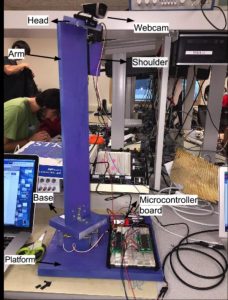
The physical platform is comprised of a webcam (Rocketfish HD) that rests atop an arm extending vertically from a base structure. The arm is attached at the base to a servo that rotates the arm and allows for panning motion. At the top of the arm is a hinge that is also attached to a servo, which rotates the hinge and allows for tilting motion. The webcam is attached to this hinge, giving it two dimensions of movement. To control these servos, we use an ATmega1284P microcontroller to receive commands from the system control module and form a servo control output using a pulse width modulation (PWM) signal.
The system control module runs on the laptop computer and performs all image processing steps, including facial recognition, brightness and contrast adjustments, and centering logic. Depending on the location and number of faces in frame, the program will emit a command to move the camera left or right, and up or down if necessary. The control module also provides a GUI to visualize the current position of the camera, and set user defined preferences.
We chose this design structure for two reasons. First, it decoupled the logic of the control module from the control of the robot movement. This made debugging separate pieces of the system easy, since we could ensure that the correct commands were being sent from the control module, then ensure that the microcontroller was forming the correct servo control outputs to move the robot. Secondly, it takes advantage of the processing power of both modules, by performing the image processing steps on the laptop computer, and the movement control logic on the microcontroller.
2.3 Hardware and Software Tradeoffs:
The hardware component of our system consists largely of the two servos controlling the pan and tilt movement of the robot. The bulk of our project lies in software, both on the microcontroller and the laptop control module. This design was a clear choice, because the selfie robot does not require any complex hardware integration beyond physical movement.
2.4 Standards:
There are several standards relate to facial detection and image processing. One of them is ISO 12233:2000: photography–electronic still picture cameras– resolution measurement. This standard specifies methods to measure the resolution of electronic still-picture cameras. Our system includes processing. It detects subjects like human faces and potentially any subjects that is compatible to the open C.V. library. Another standard that is relevant to Selfie bot is ISO/IEC 19794-5 which is for information technology — Biometric data interchange formats. This standard describes interchange formats for several types of biometric data. And for ISO/IEC 19795-5 specifically defines a standard scheme for codifying data describing human faces.
2.5 Existing Relevant Works:
There are not existing projects in the market that are extremely similar to Selfie bot. However, we are aware that there are two relevant projects that are in the similar field Selfie bot. Either of the projects have patents now and they are exploring more complex system.
Gosphero selfie robot:
Gosphero develops a selfie robot concept that could autonomously fly around and follows certain subjects around and automatically takes picture of the subject. It also automatically uploads the picture tos social media. However, this is still an undeveloped concept and they do not own any patent for this project yet.
Jibo:
Jibo is released as a proof of concept on youtube TechCrunch. Jibo is described as a social robot that helps family to stay connected in the home. The robot recognizes faces and voice and helps deliver messages to family members, take pictures and even could order your take out. While this idea is promising, Jibo considers more complicated system than Selfie bot. We are not sharing the same competing market. In addition, they do not currently own patents yet so we could still apply for patents for Selfie bot.
3.1 Summary
There are two major components of this selfie bot: facial detection and mechanically face tracking. Facial detection is processed via Phython using open CV library. After the facial detection determine that the face(s) are not centered, the microcontroller will trigger the mechanical base and arm to rotate in order to locate a better position to center faces(s). The microcontroller connects to a specific serial port to the computer. Then the program sends commands to the microcontroller for operations of either rotation of the base and tilting of the shoulder. The following figure shows the whole structure of the selfie bot system. The selfie bot is composed of platform,base, protoboard, arm, shoulder and head.
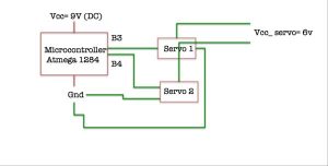
3.1 Power
Microcontroller requires 9V power; considering the mobility of this project, we use a 9V battery to power the device. Servo requires 6V power; we use 4 1.5V batteries in parallel to power two servos. The battery packs are located next to the microcontroller board on the platform.
3.2 Mechanical Arm and Base
There are a base and an arm controlled by two separate servos. Servo is a motor used to provide control of a desired operation through the use of feedback. Servo provides 180 degree range of motion and position control for this selfie bot system. There are three pins: signal(input), power supply and ground.
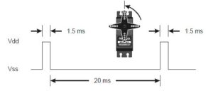
3.3 Servo
The Parallax servo is controlled through pulse width modulation, where the position of the servo shaft is dependent on the duration of the pulse. The servo needs to receive a pulse every 20 ms. The base servo is connected to B3 and the arm servo is connected to B4. In order to properly perform the face tracking feature, the base would rotate left and right for 180 degrees while the upper arm servo rotate up and down concurrently. The upper arm servo controls the tilting of the webcam. The selfie-bot could take in parameters like how many people will be in the selfie. For example, the user input two people for the selfie. Then in the next 15s, the selfie-bot would try to find the biggest two faces in the picture. Once it center to faces, one selfie will be taken.
3.4 LCD Display
In addition, we adopted LCD display for debugging purposes.
3.5 Challenges
Building the mechanical structure of this system was challenging. We had come up with several designs. We consider complexity, stability and weight of the mechanical structure. We were concerned that it would be hard to the servo to support the arm, shoulder, head and still be stable. In order to solve this problem, we use four small pieces of wood and glue it to the platform. Each wood piece has approximately the same height as the servo and they serve as support for the servo. If the upper arm tilts, the base would be strong enough to prevent further tilting.
Software
4.1 Software structure:
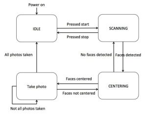
The software component of this system is comprised of two main subcomponents: the image processing and system control module running on the laptop computer, and the movement control module running on the microcontroller. The user may also specify a number of parameters. The software components are organized as a state machine that transitions between the following states:
IDLE: No action
SCANNING: The system continuously scans by panning and tilting back and forth until faces are detected. If the number of people specified are not in the picture, searching will time out after a specified wait time and just search for at least one person to take a picture of.
CENTERING: Issues commands to center the faces present in the picture
4.2 User parameters:
Contrast [0, 1]: Image contrast. Default 0.5.
Brightness [0, 1]: Image brightness. Default 0.5.
Horizontal Center [0, 1]: The position at which the program will center a face horizontally. Default 0.5.
Vertical Center [0, 1]: The position at which the program will center a face vertically. Default 0.6.
Number of people: The number of people that the system will search for. If there are more people in the frame than desired, the program will only consider the most prominent faces. Default 1.
Number of pictures: The number of pictures that the system will take before stopping. Default 2.
People search timeout: How long the system will spend looking for the specified number of people before centering on any available faces. Default 10 sec.
4.3 Image Processing and System Control:
The image processing module is implemented in Python and takes advantage of the OpenCV library, which provides the facial detection algorithm and interfaces with the webcam.
Facial detection is performed using Haar Cascades, which makes multiple passes on the image to look for different groups of features indicative of the presence of a face. This method speeds up the detection considerably by reducing the number of features considered on each pass. The cascade classifier that comes with OpenCV takes an xml configuration file as an input, which is the classifier configuration result from training on a set of images. We are using the default facial detection training file provided by OpenCV, haarcascade_frontalface_default.xml. The classifier is extendable to any configuration file, meaning that the detection algorithm can be applied to detect any desired object that has been trained on, simply by swapping out the xml file.
To reduce possible misclassification instances, we set the minimum face width and height dimensions to be fraction of the frame size in pixels, with a default of 10%. The program ignores all faces detected that are smaller than this proportion.
The bulk of the image processing logic takes place in the looped function process_image_step(), which is invoked every 200ms. This function captures a frame from the webcam, performs facial detection, and applied brightness and contrast adjustments to the image. There are two possible cases for facial detection:
- If no faces or not enough faces are detected, the program will emit a scan command. If the search timeout is reached, the program will begin to look for the first possible face, and transition fo the centering state if found.
- If it detects faces, it will then consider the face positions in the frame along with the provided parameters to define a center point. If multuple faces are detected, the center point will be taken as the midpoint between the minimum and maximum x and y face edges. Next, it determines the direction of movement required to reduce the camera center offset from that point within a specific precision, defined as a fraction of the frame size in pixels.
Finally, it will emit a command signaling this required direction of movement. The commands are formatted as l for left, r for right, u for up, d for down, and sc for scan. As described in the hardware section, the command is communicated via the serial port.
If the desired subjects are centered in the picture for 2 seconds, the app takes a picture of the current camera frame, and saves it to a specified directory.
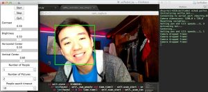
GUI application:
The GUI is implemented using TKinter, a standard Python GUI package that allows for simple input widgets. The interface has setting controls for each of the user preference parameters defined above, and allows for start, stop, and quit actions for controlling the robot. In addition, the camera frame is displayed in a separate window, with detected faces surrounded by green rectangles.
4.4 Movement Control:
The movement control logic is implemented on the ATmega1284 microcontroller. To handle the process of receiving input from the image processing module via serial communication and perform the action to move the robot, we use the Tiny Real Time (TRT) concurrency library to define separate processes for these operations.PWM for servo control:
The movement logic revolves around outputting a PWM signal to control the two servos for panning and tilting, as described in the hardware section. To form this signal, we used timer3 on the microcontroller to invoke an interrupt every 0.025ms. Specifically, we run the timer at full speed (16MHz) in Clear Timer on Compare Match (CTC) mode, with an output compare register value of 399, which gives a interrupt frequency of 40KHz, using formula below, where the f_clk_i/o is the clock frequency, f_OCnx is the timer interrupt frequency, and OCRnx is the output campure register value:
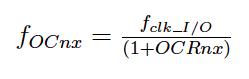
Since the servos specified a turning range corresponding to 0.75 – 2.25ms, this timing scheme gave us a positioning resolution fine enough to reasonably center the subject as desired in the camera frame.
The actual signal was constructed as a manual PWM. The servos required a signal at a rate of 50Hz (every 20ms), so we specified a cycle duration of 800 ticks using our timing scheme, incrementing a cycle_time variable on each timer interrupt. We defined the following constants for the desired movement bounds as a number of ticks:
MAX_LEFT: 80
MAX_RIGHT: 20
MAX_UP: 48
MAX_DOWN: 28
This timing was in practice slightly different than specified by the servo documentation, which we discovered from experimentation. To change the duty cycle of the signal, we kept track of pan_signal_time and tilt_signal_time, which specified the number of time ticks the signal would be output high. Finally, to construct the PWM signal, we set the output high when the tick time was under the desired signal time during each cycle, and low otherwise. We used ports B.3 and B.4 for panning and tilting outputs respectively.
[PWM trace plot(s) and timings] Serial Input:
We defined the TRT task void pollInput(void* args) to continuously poll wait for serial input. Receiving a sc command causes the controller to enter the scanning state, and receiving any of l, r, u, d causes the controller to update the current command in the variable action_cmd.
Movement actions:
Movement is handled by the TRT task void performAction(void* args), which runs every 300ms. In the SCANNING state, the controller continuously increments pan_signal_time and tilt_signal_time, changing directions when it reaches its movement bounds. In the CENTERING state, the controller examines the action_cmd variable and increments or decrements pan_signal_time and tilt_signal_time appropriately.
TRT:
Taking advantage of the TRT library allowed us to separate the processes for receiving input and performing the movement adjustments. This allows for efficient non-blocking communication with the image processing module and gave the program flexibility with respect to setting the timings of sending and receiving commands and actually controlling the movement. The commands are received from the image processing module every 200ms to ensure an updated version of camera feedback, however movement actions are performed every 300ms to give the camera slightly more time to focus, since there is some motion blur and focus time. We adjusted these timing parameters to produce the fasted operation given our image processing speed and camera hardware.
Results
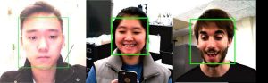
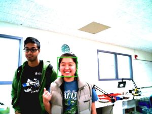
The system operated as expected, centering faces and taking pictures according to the user defined parameters. The pictures were saved to the directory with the appropriate contrast and brightness properties. Some examples captures are shown below with their respective preference parameters:
As demonstrated, the selfiebot works with multiple people, centering the image depending on the midpoint between all of the detected faces. It also correctly centers faces when the horizontal and vertical center are modified by the user.
In addition, the our robot handles the number of specified people correctly. If there are too many people in the picture, it only considers the most prominent faces and ignores the rest. If it cannot find the specified number of people, it searches for a set timeout period. When this timeout expires, it begins to search for anyone to take a picture of and disregards the parameter specifying the number of people.
5.1 Speed of execution:
The speed of the robot in detecting and centering subjects was reasonable for test purposes. The system typically took 5 seconds to find the subject and once found, around 5 more seconds to center and take a picture. Practically, these wait times are ok for standard posing pictures, considering that self-timer delay options for many digital cameras default to 10 seconds. However the numerous other potential applications of this system, including capturing performances, athletics, and security, would benefit from a much faster operation time.
Our main limitation in the speed of operation was that the particular webcam we used did not handle sharp movement well and took some time to refocus. This caused us to have to slow down the timing and movements of our robot to compensate. Most likely, the high resolution of the camera made it more difficult to refocus quickly, but we were unable to find a way to reduce the resolution. Since we used a Mac, we couldn’t install the drivers on the computer to modify this either. This issue can be mitigated by replacing the webcam with one more suited to quick movements.
If we consider the maximum speed of the program, the process on the laptop was fast enough to run in under 100ms on average, even with a high resolution of 1600 x 1200. This included facial detection, image processing, centering logic, and writing to the serial port. The microcontroller is also able to match this speed. Thus, the limitations in speed are bound entirely by the camera focus speed and the servo movement speed.
5.2 Accuracy:
The selfiebot was able successfully center and capture faces with a precision of 10% of the camera frame, which we found to be reasonable for most situations. At higher precisions, the camera would sometimes spend a longer time attempting in the centering step because the camera would rotate too far in one increment, causing it to move back and forth continuously around a subject. As mentioned in section 4.4, our servo control timing scheme gave us a resolution of 0.025ms for adjusting the PWM duty cycle, which limited how accuracy we could get with the rotation of the servos. If a higher accuracy was desired, we would lower the output compare register value to give a timing higher resolution and for more precise movements.
Facial detection provided by OpenCV did an excellent job of detecting most faces in the frame, however there were some cases in which it was not as effective, including angled faces, thick facial hair, and accessories (hats, glasses). This detection could be improved by training the classifier on a larger and more diverse set of examples. Our program uses training data specified by a configuration file that is read into the face detector class. This configuration file can be easily swapped out for a different one that is trained for more detailed detection.
5.3 Safety:
Our robot does not contain any dangerous components. The only two moving parts are for rotating and tilting the camera, and the speed of these movements poses no threat to people around it. The device is powered by one 9V battery and one 6V battery holder pack, so any possible electric shock would not be harmful.
5.4 Usability:
We designed the selfiebot with the user in mind at every step to make it as easy and flexible as possible to use, given what we determined to be the most important preferences that someone would have when operating our system. We provide a simple and informative GUI on the laptop computer to set a number of preferences. The user can adjust contrast and brightness with an intuitive scroll bar that ranges from 0 – 1, and choose the exact spot they they would like to appear in the photo by changing the horizontal and vertical centering parameters. They can also specify the number of people in the photo, so that the robot will attempt to find everyone that needs to be in the picture, as well as the search timeout if the robot cannot find everyone. Last, they can specify how many picture to be taken, since it’s like that people wouldn’t want to the robot to keep taking photos non-stop. The GUI also displays the currently camera frame, and the faces detected, giving the user a clear indication of what the robot is seeing and how it is reacting to them.
Other parameters that would have been helpful to customize are the output directory for the photos, and the desired width and height dimensions of the outputted photo.
Conclusions
6.1 Summary:
Our project was fully functional and met our expectations in terms of performance. The speed and accuracy were satisfactory for the level we were hoping to achieve, and all components behaved as desired for any combination of user preferences settings. Overall, the results of operation were extremely positive, and the robot is a solid proof of concept for an autonomous facial tracking and picture taking system.
6.2 Future improvements:
There are a variety of future improvements that could improve and extend the functionality of the robot, many of which can be applied easily to our design given the right resources. On the software side, project could be extended to track any object in addition to faces, by training the detection classifier on a different object. The resulting xml configuration file could then simply be swapped with the current one. As an example, someone trained the same OpenCV classifier to detect bananas instead of faces. To add another dimension to the selfiebot, we could also integrate the system with facebook or some other social network so that it could automatically save and upload pictures to the user’s account.
Physically, the operation speed of the robot could be sped up considerably by choosing a camera with less motion blur and focus lag (the built in mac webcam works very well, but unfortunately it isn’t portable). Another improvement could be an extendable arm that moves up and down to adjust vertical camera position in addition to panning and tilting. To do this, we could use either an elevator, or some kind of telescoping arm. Furthermore, the platform could be made mobile by attaching wheels, so that it can actually move around and follow the subject. It’s even possible to attach the camera to a quad copter and communicate with the laptop through radio signals instead of serial, which would give the robot incredible mobility.
6.3 Standards:
Our design conforms to the applicable standard in the form of improvement and approaching the standards. We ensured that we meet the standard during the process. We were aware that our facial detection and image processing are related to certain standards. When are continuingly developing the product we are using these standards as our guidelines.
6.4 Intellectual Property:
Referenced code:
To perform facial detection in Python using OpenCV, we derived the basic implementation from the following website, which described how to use OpenCV to interface with the camera and use the cascade classifier for facial detection:
https://realpython.com/blog/python/face-recognition-with-python/
Patent Opportunity:
There is a patent opportunity for our device, for an automated facial tracking and photo capture system. There are currently other patents for automated photo capture systems, but they use other methods of identification, such as RFID, and do not perform tracking.
Jibo recently filed a patent application for a persistent companion device that also takes pictures of people, but does not specify the manner in which photos are taken or how it detects people. This application has not yet been accepted.
6.5 Ethical Considerations:
We are aware that our project is indeed affecting and have a possibility of improving people’s life. We recognize and agree that we agree to the IEEE code of Ethics. When we first selected the topic of the project, we made sure that we are not developing anything dangerous for the society. We never consider projects that might be able to be developed as weapon. We really like the idea of selfie robot because people are really active on social network. People could use this selfie robot to connect better with friends and utilize more technology for social platfroms. We are aware that we must disclose any conflicts of interest whenever possible. Throughout the process we were honest and realistic when speaking about claims and data. We were well aware that we treat all persons equally and not engage in any act of discrimination based on race, religion, gender, identity or gender expression. We also maintained and tried to improve our technical competence. We also tried to improve the understanding of technology. We understood that selfie robot is an appropriate application and it would have great potential to encourage individuals to use more technology in daily life. We also never injure others or their property or reputation.
6.6 Legal Considerations:
This project does not use RF components, is low power, and does not cause harm to individuals in any way, so there are no legal concerns with regard to our design.
A. Schematics:
Source: Selfiebot