Summary of The simplest digital voltmeter with AVR
This article describes a simple digital voltmeter project using an Atmel AVR ATmega8 microcontroller. It features a three-digit multiplexed seven-segment LED display for voltage readout up to 10V, with an optional 100V range via resistor modification. The device uses the ATmega8’s 10-bit ADC to measure voltage, displaying values from 0 to 999, with "---" indicating overflow. The display brightness is controlled by resistors, and decimal points can be enabled via jumpers. Calibration is done with a trimmer potentiometer, and the system runs on a 5V supply with an internal 1MHz oscillator and a refresh rate around 4Hz.
Parts used in the Simplest Digital Voltmeter with AVR:
- Atmel AVR ATmega8 microcontroller
- Three-digit seven-segment LED display (T-5631BUY-11, yellow)
- Resistors R1 to R8 for LED current limiting
- Resistors R9 and R10 for voltage divider
- Trimmer potentiometer P1 for calibration
- Jumpers DP1 and DP2 for decimal point control
- Power supply (~5V)
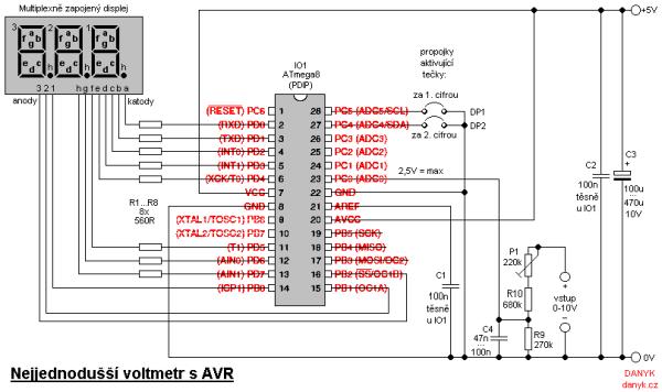
This is probably the simplest possible digital voltmeter with Atmel AVR microcontroller. The circuit is controlled by a microprocessor IO1 – Atmel AVR ATmega8 (ATmega8, ATmega8L), a program to download and configuration bits setting is below. (ATmega8 may seem too “big”, but was chosen because it is one of the most frequently used AVR and is often can be found in a drawer.) The three-digit seven-segment LED display is used to display the value.
Cathodes are connected to port D, anodes to the lowest 3 bits of port B. Using the suberbright display allows to omit the current amplifying transistors. The display is controlled by multiplexing (matrix) and connected the usual multiplex way. I used three-digit yellow display T-5631BUY-11 with 150-200mcd luminosity. The resistors R1 to R8 determine current into display and thus its brightness. They are chosen not to exceeded the maximum output current (40 mA) even when all 8 LEDs lit at once. The circuit uses single ended 10-bit ADC (analog-digital converter) in AVR. The output values range from 0 to 1023, but because is not worth adding a fourth digit for the narrow range of 1000 – 1023 the range is limited to 0 – 999. A higher value will appear the symbol “—“. The range of the voltmeter corresponds to input voltage of 2.5 V. The input is connected via a divider of 1/4 consisting of R9, R10 and P1, providing 10V range with resolution to 0.01 V. Input impedance is approximately 1M. (If you need the 100V range, modify the R10 value to 9M1 and P1 to 2M2. Then you’ll have 100V range with a resolution of 0.1 V and the input impedance of about 10M.) Voltmeter calibration is performed according to a known voltage by setting the trimmer P1. DP1 and DP2 jumpers may be used to light up the decimal points. DP1 lights up a decimal ponit after the first number (0.00), DP2 lights up dot after the second number (00.0). Refresh rate of the voltmeter is about 4Hz. IO1 uses the internal RC oscillator that is set to 1MHz. The circuit is powered from a supply of about 5V.
Read More: The simplest digital voltmeter with AVR