Summary of Universal Serial Bus (USB) Connectors Pinout
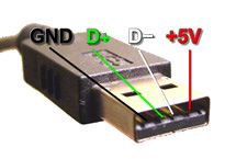
This article explains the Universal Serial Bus (USB) connectors and their pinout configurations. USB cables have standardized wiring with four main pins: VCC (+5V supply), D- (negative data signal), D+ (positive data signal), and GND (ground). USB simplifies connecting peripherals like mice and printers to computers by providing a universal, easy-to-use interface that supports up to 127 devices. The cable contains two power wires (red for +5V, brown for ground) and a twisted pair of data wires (yellow and blue), all surrounded by shielding to ensure reliable signal transmission.
Parts used in the USB Pinout Diagram:
- VCC (Supply Voltage, +5V)
- D- (Data Negative Signal)
- D+ (Data Positive Signal)
- GND (Ground / Neutral)
- USB Cable (including red, brown, yellow, and blue wires)
All Types of USB Pinout Diagrames
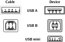
Universal Serial Bus connectors. These USB connectors let you attach mice, printers and other accessories to your computer quickly and easily. The operating system supports USB as well, so the installation of the device drivers is quick and easy, too. Compared to other ways of connecting devices to your computer (including parallel ports, serial ports and special cards that you install inside the computer’s case), USB devices are incredibly simple.
PC Cable USB Pinout Diagram
Other USB Connector Pin out
| Pin No. | Signal/Symbol | Notes | Description |
|---|---|---|---|
| 1 | VCC | Supply Voltage | +5V |
| 2 | D- | Data -ive Signal | Data – |
| 3 | D+ | Data +ive Signal | Data + |
| 4 | GND | Ground / Neutral | Ground |
Inside a USB cable:
There are two wires for power — +5 volts (red) and ground (brown) — and a twisted pair (yellow and blue) of wires to carry the data. The cable is also shielded. The goal of USB is to end all of these headaches. The Universal Serial Bus gives you a single, standardized, easy-to-use way to connect up to 127 devices to a computer.


