Summary of How to use I2C / TWI (Two Wire Interface) in AVR ATmega32
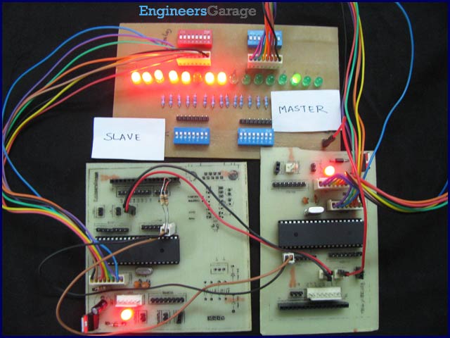
This article demonstrates TWI (Two Wire Interface) communication between two ATmega32 microcontrollers, where one acts as master and the other as slave. The master sends data starting from 0x01; the slave returns the complemented data. The master then shifts the original data left and continues this exchange. Received values are displayed on PORTB at both ends. The article explains TWI modes, initialization, start condition transmission, and addressing using ATmega32's built-in registers and TWI control.
Parts used in the TWI interfacing between two ATmega32 controllers:
- ATmega32 microcontroller (two units)
- Connecting wires
- Power supply for microcontrollers
- Common ground connection
- PortB connected output devices (e.g., LEDs or display units)
This article explores the TWI interfacing between two ATmega32 controllers. Readers are advised to go through TWI Communication and TWI registers of ATmega32 before going further.
TWI works in four modes:
1. MASTER as a transmitter.
2. MASTER as a receiver.
3. SLAVE as a receiver.
4. SLAVE as a transmitter.
Generally modes 1 & 3 and modes 2 & 4 are used together. This article explains the use of these four modes by an experiment.
Objective: To establish the communication between two ATmega32 using TWI interface. First the Master starts by sending data then the slave transmits complement of the received data to the master. When the Master receives the complemented data, it shifts the original data to left. This process of transmitting and receiving continues. As the data value reaches 0x80 the whole process is repeated. At the starting, value of the original data is 0x01. The received value is displayed on PORTB at both the ends.
Circuit description:
Make the connections as shown in the circuit diagram.
Code explanation for MASTER Controller:
Step 1: Initialization of master.
Initialization of MASTER means to set the TWI clock frequency (SCL). It is done by setting bit rate in TWBR and pre scaler bits in TWSR.
void TWI_init_master(void) // Function to initialize master
{
    TWBR=0x01;    // Bit rate
    TWSR=(0<<TWPS1)|(0<<TWPS0);    // Setting prescalar bits
    // SCL freq= F_CPU/(16+2(TWBR).4^TWPS)
}
Step 2: Send start condition
The start condition in TWI is explained before. The AVR microcontroller has in built registers which makes this job much easier.
1. Clear TWINT flag by writing a logic one to it.
2. Set TWSTA bit to send start condition.
3. Set TWEN bit to initialize the TWI.
4. Monitor the status of TWINT flag.
5. Check the ACK byte (using while condition since the SCL frequency is very small as compared to micro controller clock frequency). The ACK byte can be compared by monitoring the status of TWSR.
void TWI_start(void)
{
    // Clear TWI interrupt flag, Put start condition on SDA, Enable TWI
    TWCR= (1<<TWINT)|(1<<TWSTA)|(1<<TWEN);
    while(!(TWCR & (1<<TWINT))); // Wait till start condition is transmitted
    while((TWSR & 0xF8)!= 0x08); // Check for the acknowledgement
}
Step 3: Send the slave address, data direction bit (write) and wait for the ACK signal
These three processes are controlled by AVR’s TWI registers.
1. Put the seven bit slave address and the direction control bit in TWDR.
2. Clear TWINT flag.
3. Enable TWI by writing logic one to TWEN bit.
4. Monitor the status of TWINT flag, the TWINT flag will get cleared when the data in TWDR is been transmitted.
5. Check for the correct acknowledgement.
void TWI_read_address(unsigned char data)
{
    TWDR=data;    // Address and read instruction
    TWCR=(1<<TWINT)|(1<<TWEN);    // Clear TWI interrupt flag,Enable TWI
    while (!(TWCR & (1<<TWINT))); // Wait till complete TWDR byte received
    while((TWSR & 0xF8)!= 0x40);  // Check for the acknoledgement
}
For more detail: How to use I2C / TWI (Two Wire Interface) in AVR ATmega32