Introduction
This project was designed to aid a research study by Cornell Professors Bob Nafis and Yingxin Gao on the reasons behind the higher rate of ACL injuries suffered by female athletes. This injury rate can be up to three to eight times higher than the rate of similar injuries suffered by male athletes. The project focuses on creating a set of electronics using an Atmel ATmega324P microcontroller that can be worn on soccer cleats to measure shocks to the foot during play.
Using an accelerometer to measure the acceleration of the foot during walking, running, and play, we send gathered data via a wireless XBee connection to another microcontroller connected serially to a computer. Importing the data into Matlab, we are able to plot and analyze the data, comparing to different thresholds of walking and running. The purpose of the project is to compare data obtained during athletic activity with normal activity to see if there are any differences in acceleration that the foot experienced that could have caused or lead to an ACL injury.
High Level Design
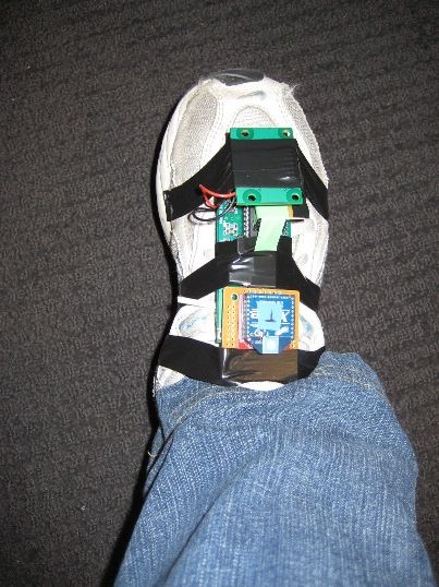
There are two main components of the project. The accelerometer sensor that is attached to the foot along with a transmitter, and the receiver station attached serially to the computer.
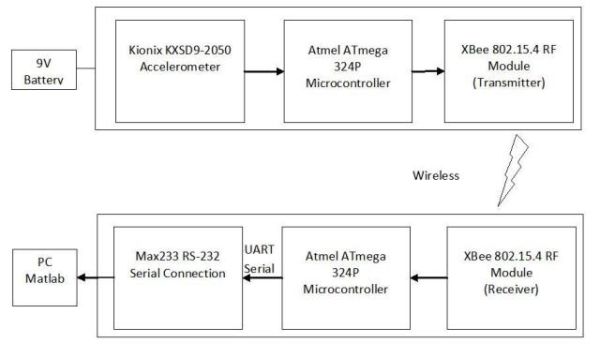
The accelerometer sensor consists of a Kionix KXSD9-2050 three-axis accelerometer, XBee wireless transmitter, and an ATmega324P microcontroller. The receiver station consists of an XBee wireless receiver, ATmega324P microcontroller, and Max233 chip for RS232 serial communication. The sensor takes acceleration data from the accelerometer, creates packets of 15 sampled data points along with the time they were obtained, and transmits the packets wirelessly to the receiver. The receiver then parses the packets and responds when Matlab requests data over the serial port. The high level design is shown in the following block diagram.
Hardware Design
The two major hardware components of the project are the wireless connection implemented through XBee transmitters and the accelerometer to determine acceleration of the foot during walking and running. Because we require two UARTS to simultaneously interface with the XBee and the serial, we decided to use the Mega 324P microcontrollers because they have two hardware UARTS, as opposed to writing a software UART.
Because both the XBee transmitters and the KXSD9-2050 accelerometer run at 3.3 V, we designed our MCU prototype boards with a 3.3V regulator (LP2950CZ-3.3-ND) to obtain the correct Vdd for the project. On the sensor end, the accelerometer was connected to the SPI pins on PORTB and the XBee was connected to UART0 through pins D0 and D1.
On the PC end of the project an additional connection to the computer through a MAX233 chip and serial port is required. Since UART0 on the microcontrollers is reserved for the XBee modules, the RS232 connection is through UART1. Schematics of the two systems can be found in the appendix.
XBee Modules:
We implement a wireless connection in our project to transmit data from a wearable accelerometer on the foot to a computer for analysis. This connection is made with two on-chip antenna XBee wireless modules (XB24-ACI-001) operating at 1mW transmitting power. They interface with the microcontroller through the UART and operate in the XBees API mode. Both receiving and transmitting XBees are configured with AT commanding to have the following properties, allowing for correct transmission:
- 38400 baud rate
- API mode enabled
- Module local address is set to enable 64-bit addressing
- Channel Mask set to 0x1000 to only transmit and receive on channel 15
- Sleep Mode set to 1 on the transmitter side to enable Pin Hibernation when there is no useful accelerometer data (when the person is standing still) to save power. This reduces current draw from 200 microAmps to <10 microAmps.
Since the XBee transmitters interface with the UART on the microcontroller, we chose to use the ATmega324P which has two built-in UARTS. The XBee interfaces with UART0 on the Mega 324P microcontrollers and on the receiver end, the serial to PC RS-232 interface interfaces with UART1. Dout on the XBee is connected to the RX pin of the corresponding UART and Din is connected to the TX pin. The XBee’s also have a pin spacing of 2mm which is incompatible with the 0.1″ standard spacing on solder boards. To convert the spacing, we used a breakout board (BOB-08276) and 2mm sockets (PRT-08272) obtained from SparkFun that converted the 2mm pins of the XBee to 0.1″ headers to attach to our project.
Kionix KXSD9-2050 Accelerometers:
The KXSD9-2050 is a three-axis accelerometer that we use to gauge foot acceleration during walking and running, which relates to effects felt by the knee due to foot impact and twisting. Since the accelerometer comes in an un-solderable by hand 3x3x.9mm LGA package only, we use a Kionix pre-soldered evaluation board to interface the accelerometer with the SPI on the microcontroller. Datasheets and schematics for the accelerometer, evaluation board, and pin numberings can be found in the appendix. The appropriate SPI lines are connected through PORTB on the microcontroller. The accelerometer is configured through two control registers, reg_B and reg_C, set during initialization and the following configuration is used in this project:
- 4g range scale with a 12-bit sensitivity of 410 counts/g
- A Motion Wake-Up Threshold of 2g
- A Filter Corner Frequency of 50 Hz (the operational bandwidth of the accelerometer)
Hardware Difficulties:
The trickiest part of the hardware design was getting the accelerometers to work. When we first tried the accelerometers, we received junk as output and could not find anything wrong with the SPI code. We tried all different combinations of clock polarity and clock phase to determine if it was a timing issue, but the results didnt change. Since all of these did not work, we assumed that the accelerometers may have been blown since we had accidentally run them at 5V although they were only rated for 3.3V. We ordered replacement parts, but saw the same effect as before: capacitive coupling between SCLK and the HI-Z output. After many headaches, we finally were able to discern the problem.
Since pin numbers on the Kionix evaluation board schematics were unnumbered, we first assumed that it followed usual (MCU) convention with pin numbering 1 through 7 down the first column followed by 8 through 14 up the next column. This was incorrect, however, as the pin numbers actually increased across the rows instead of down the columns. Due to incorrect pin connections, the accelerometers had not been attempting to receive or send data, and were not even powered up. After encountering the same problem with the new accelerometers, we discovered the incorrect pin connections after close examination of the the schematics. Figure 2 shows the actual pin numbering of the evaluation board.
We also ran into problems using the XBee wireless modules. After solving basic software connection problems, we were able to transmit and receive, however it was very unreliable, with a very high percentage of packets getting dropped. Sometimes it would start on power-up, and other times, we had to keep resetting until we could find a connection. Sometimes it wouldn’t work unless we power cycled the receiver XBee module by unplugging its power cables and then plugging them back in to start receiving. To solve this problem, we first tried to reduce the channel scanning time by only transmitting and receiving on channel 15. This helped a little bit as we were able to find a connection more often than before, but it was still unreliable on restart and power up of the microcontrollers. The eventual solution was to increase the baud rate of the XBee modules. Originally we were running them at 9600 baud rate to coincide with the UART baud rate for simplification. By changing the baud rate to 38400, a 4x increase, we decrease the percentage error caused by running the MCU at 16MHz. At a baud rate of 9600, there are .0006 bits received/cycle, while at 38400, this increases to .0024 bits/cycle, so the receiver has a lower error rate. Once we changed the baud rate to 38400, the XBee wireless connection became completely reliable, and a connection is immediately established if both transmitter and receiver are powered up at the same time.
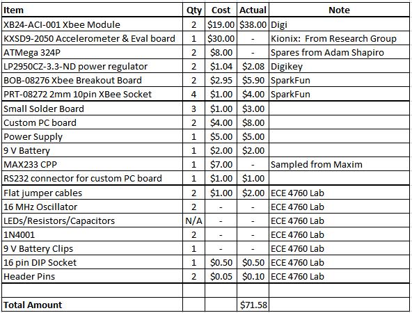
Parts List:
For more detail: ACL Research: Foot Acceleration Sensor Atmega324p