Summary of Audio Spectrum Analyzer Using Atmega644
The project is an audio spectrum analyzer using two Atmel Mega1284 microcontrollers to visualize audio frequencies up to 4 kHz on a black and white histogram via an NTSC TV. One MCU handles audio acquisition and FFT processing while the other generates real-time video output and handles user input through push buttons. Audio signals are input via a 3.5mm jack, amplified, filtered, and processed, with video output via composite NTSC signal. Communication between MCUs uses USART. The design and hardware optimize signal quality and user functionality within a compact, cost-effective setup.
Parts used in the Audio Spectrum Analyzer:
- Atmel Mega1284 Microcontroller
- LCD TV
- SIP/Header Pin
- DIP socket
- Custom PC Board
- 6 inch Solder Board
- RCA Video Jack
- RCA Video Male-to-Male Cord
- 3.5mm Audio Jack
- 3.5mm Male-to-Male Audio Cord
- 3.5mm Audio Splitter (Male to 2x Female)
- Push Button Switch
- Texas Instruments LM358 Op-Amp
- Resistors, Capacitors, and Wire
Our ECE 4760 final project was an audio spectrum analyzer that would display a histogram-style visualization of an audio signal. We were able to successfully display the frequency spectrum content of an audio signal in real-time using a black and white histogram visualization with bins arranged from left to right corresponding to low to high frequency ranges using a system based upon two Atmel Mega1284 microcontrollers.
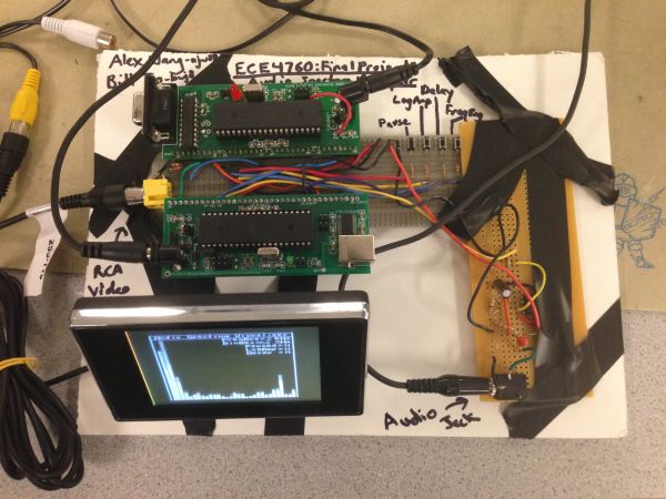
The two microcontrollers handled separate tasks, with one performing the audio data acquisition and processing (hereafter referred to as the FFT MCU) and the other performing the visualization processing and video data transfer (hereafter referred to as the Video MCU). Users are able to select various display options using a set of push buttons including the overall frequency range displayed and the amplitude scale, among others.
Using a male-to-male 3.5mm audio cable, the user can connect any audio producing device such as a computer or MP3 player to the device’s 3.5mm audio jack and input an audio signal. Using a male-to-male RCA video cable, the user can connect any standard NTSC television supporting resolutions of at least 160×200 to the device’s RCA video jack and display the visualization on the TV.
Our device is able to display frequencies in audio of up to 4 kHz, which covers the majority of the frequency range of typical music which is the intended input of our project, as shown in this diagram.
High Level Design
Rationale & Inspiration
Our project idea was inspired by popular toys such as the T-Qualizer, and built in music visualizers in many software audio players such as Windows Media Player. We wanted to create a similar hardware based equalizer that could be built cheaply and interface with standard audio inputs and video outputs. We originally wanted to take audio input with a microphone but realized that input directly from another device offers clearer signals. Being able to view a visualization of the frequency spectrum of audio is both interesting as a visual entertainment source to pair with music as well as a way to view the different frequency components assoicated with certain sounds or instruments. For example, one can see not only the main pitch of a note from an instrument such as a saxophone but also the various harmonics that determine the timbre of the instrument.
Overview
The data flow of our project runs rather linearly. First, the audio signal is inputted into the system through the audio jack. The signal is amplified and filtered and sent to the FFT MCU. This microcontroller will sample the audio signal at a constant rate and perform a Fast Fourier Transform (FFT) to convert the signal into frequency domain. This frequency domain data is transmitted to the Video MCU, which processes the data into a histogram visualization in real-time. Various user options can be changed via push buttons allow the user to modify the display as desired. Finally, the Video MCU transmits a composite video signal to the TV.
Regarding communication standards, we used the NTSC analog television standard to output black and white video to our NTSC compatible television. NTSC (National Television System Committee) is the analog video standard used in most of North America. This standard defines the number of scan lines to be 525, two interlaced fields of 262.5 lines, and a scan line time of 63.55uS. The standards set by NTSC are closely considered in our project when creating the composite video signal to output to our TV.
While not technically a standard, we also used USART to serially transmit data between our two MCUs. The Atmel Mega1284 MCU has various frame formats that must be followed in both the transmit and receive MCUs including synchronous mode which we used. USART are often used with communication standards such as RS-232 but were not used in our project.
Hardware
Introduction
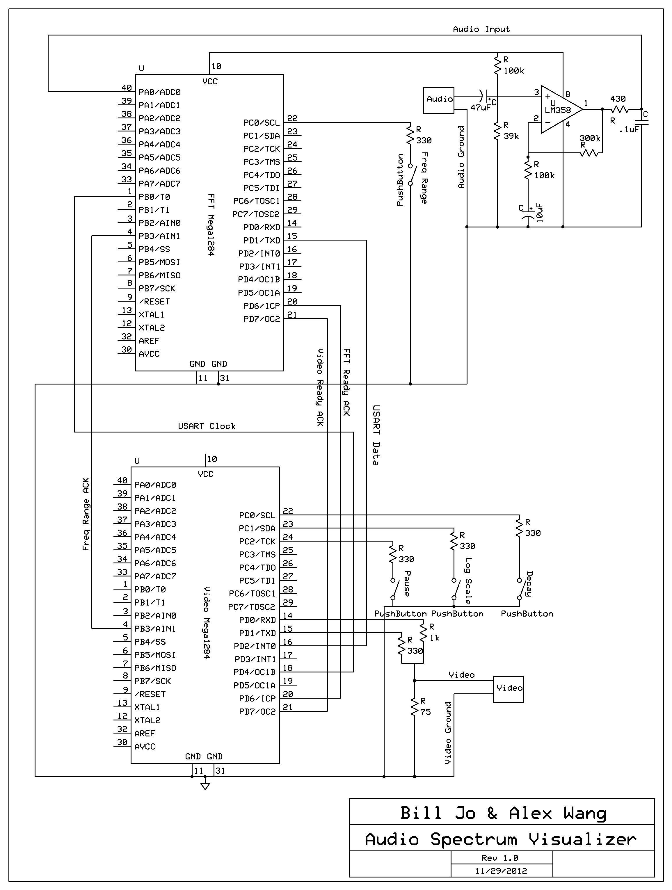
The hardware portion of our project includes the two MCUs with USART connections, the hardware amplifier and filter circuit for the audio input, push buttons for user controlled input, and a DAC circuit for video output.
Audio Amplifier and Filter
First of all, we needed to calculate the input bias voltage offset for the analog audio signal to meet our requirements. There were two factors in this calculation: the range of the amplifier and the ADC reference voltage. The ADC reference voltage is the voltage corresponding to the maximum value of the ADC (255) and any voltages above this returned the maximum value. We knew that range for this amplifier was from 0-3.5V and ADC reference voltage had built in values of 1.1V, 2.56V, and 5V. We chose to use 2.56V because 5V gave us about half the resolution and values equating to voltages above 3.5V would never be used, and 1.1V would not utilize the majority of the range of the op-amp. Therefore, we decided to set the DC bias voltage to 1.28 to fully utilize the ADC range and to put the input signal within the op-amp range so that there are no negative voltages. To achieve this, we built a voltage divider using 100kΩ and 34kΩ resistors. Unfortunately, we were unable to find a 34kΩ resistor and opted to use a 39kΩ instead, raising our DC bias voltage to 1.4V.
We used the Texas Instruments LM358 op-amp as the main amplifier component. Using a non-inverting amplifier circuit, we set the gain of the amplifying circuit to 1+(300kΩ/100kΩ) = 4. Initially, when we were using the microphone as the input, we had the gain set around 10 to amplify the weaker audio signal when an external audio source was used (since the microphone needed its own voltage source to power itself, the microphone signal was much stronger than the external source’s signal). However, after we decided to exclusively use audio directly from an external audio source, we reduced this gain as these audio signals are larger and can be easily adjusted. We were frequently reaching the op-amp rail voltages with the gain around 10. We added an RC low-pass filter to remove frequencies above 4kHz to reduce aliasing. The RC time-constant corresponds to a cutoff frequency of about 3.7kHz, but it has a slow drop off and the RC filter transfer function doesn’t reach values below 0.5 until much higher cutoff frequencies, thus we wanted to set the cut-off slightly before our desired value of 4 kHz.
Push Buttons
Each push button had the same simple design. One end was connected to ground and the other to an input pin through a 330Ω resistor. The resistor was there to prevent any ports from being accidentally damaged from large current pulses. The MCU input had its pull-up resistor on, making the port (and button) active low.
Video Digital-to-Analog Converter
We used a simple DAC to combine the digital video data signal (Port D.1) and sync signal (Port D.0) to a composite analog video signal between capable of generating 3 levels: 0V sync, 0.3V black, and 1V white. This was achieved by the resistor network to the right.
The video output was connected to the inside axial pin of a standard female video RCA connector, and the outside ring of the RCA connector was grounded to the common ground of the entire device.
Data Transmission Connections
We used USART in synchronous mode to transmit data between the MCUs. This meant we needed a port dedicated to the clock and another port dedicated to data transfer from the FFT MCU to the Video MCU. There is no data transfer going in the other direction so a third channel was not implemented. Besides these channels, we also had 3 ports connected between the MCUs for communication of various flags and ready signals.
Parts List:
| Part | Cost/Item | Method Obtained | Quantity | Total Cost |
| Atmel Mega1284 Microcontroller | $5 | S | 1 | $10 |
| LCD TV | $5 | R | 1 | $5 |
| SIP/Header Pin | $0.05 | S | 1 | $8.15 |
| DIP socket | $0.50 | S | 2 | $0.50 |
| Custom PC Board | $4 | S+F | 1 | $4 |
| 6 inch Solder Board | $2.50 | S | 5 | $5 |
| RCA Video Jack | $1 | S | 1 | $1 |
| RCA Video Male-to-Male Cord | $1 | R | 4 | $1 |
| 3.5mm Audio Jack | Free | S | 2 | $0 |
| 3.5mm Male-to-Male Audio Cord | $1 | R | 147 | $1 |
| 3.5mm Audio Splitter (Male to 2x Female) | $1 | R | 10 | $1 |
| Push Button Switch | Free | S | 1 | $0 |
| Texas Instruments LM358 Op-Amp | Free | S | 1 | $0 |
| Resistors & Capacitors & Wire | Free | S | 5 | $0 |
| Key for “Method Obtained” | — | — | ||
| R=Rented, S=Lab Stock, F=salvaged/free | TOTAL | $36.65 |
For more detail: Audio Spectrum Analyzer Using atmega644