Summary of Auto-composing keyboard Using Atmega644
This project presents an auto-composing electric piano using an ATmega644 microcontroller. Users select a music mood and input two notes; the system composes music based on these, using Markov models and composing rules. A train mode allows users to customize composing by feeding their own melodies. The piano keys connect via priority encoders to manage inputs, while the MCU synthesizes piano tones using FM synthesis. Output sound is generated through PWM, filtered and played on a speaker. The design balances memory and sound quality constraints, offering an intuitive interface through a keypad and PUTTY terminal.
Parts used in the Auto-composing System:
- ATmega644 Microcontroller (MCU)
- Electric piano keyboard with 23 keys (G2 to F4)
- Three 8-to-3 priority encoders
- Keypad (for user input and mode selection)
- RC low-pass filter
- Speaker
- STK 500 development board
- Computer with PUTTY terminal (for user interface)
- 5 kilo-ohm resistors (for pull-up on keys)
Project Overview
We designed an electric piano that automatically composes a piece of music for the ECE 4760 final project. All the user need to do is to select a mood of the music and play two notes upon which the music is based, and then he can just lie down and enjoy the music created for him. He can also choose to train the piano by first playing several pieces of music he is fond of. The piano would then compose music based on the pattern of the music user just played.

High Level Design
Rationale and Inspiration
Composing has always been an almost forbidden area for people who have no systematic music trainings. Because of the complicated composing rules developed by different composers over the past hundreds of years, it could be a challenge for an amateur to create a piece of music that obeys most of the rules and thus sounds pleasant without multiple times of experimenting. Our project, “Auto-composing System”, helps solve this problem by making composing easier for non-experts.
Our project features a very friendly user interface, which include an electric piano and a keypad. It needs almost no set up and can switch between different modes easily.
Inspired by the third lab in which we used FM synthesis to generate a sequence of sound, we developed algorithms to make the microcontroller (MCU) to not only generate random sequence of piano-like sound, but a piece of “real” music that sounds pleasant and obeys most of the composing rules.
Composing Algorithm Overview
Generally, our composing algorithm takes in three inputs and consists of three stages of composing. The first input that user has to enter is the mood of music that he/she wishes to create. Currently, we support two moods: happy and tender. The other two inputs are two notes chosen by the user.
In the first stage of composing, the tone of the music is determined as a result of the three inputs. Happy mood corresponds to a major tone determined by the two input notes, while tender mood corresponds to a minor tone determined by the two input notes. The speed of the music is also determined in the first stage by the mood input.
The next stage is to create the melody for the music. The first step is to set rhythm corresponding to different moods. After the rhythm is set, the next note of the melody is chosen roughly according to the corresponding Markov probability matrix until all notes of the melody is filled. We incorporate composing rules that cannot be represented by the probability matrix to the melody composing process by either setting certain notes deterministically or changing the probability matrix when choosing notes for some special rhythm.
After the melody is set, our algorithm chooses proper chord for it. The chord is chosen so that it sounds harmonic together with the melody and also varies with some randomness to avoid monotony.
There is a special train mode in our composing system that lets the user to build his or her own Markov probability matrix instead of using our pre-trained ones. If the user chooses to enter the train mode, the system allows the user to play a piece of music on the electric piano. Then the system will compute the Markov probability matrix based on the piece of music that the user played and thus could generate music that assemblies what the user just played with some variations.
Logical Structure
There are three primary components involved with the system: the input devices, the ATmega 644 MCU and sound output device.
The input devices consist of two parts: the piano input and the keypad. The piano consists of 23 keys ranging from G2 to F4 that user can play. The keys are divided into 3 sections and are treated as independent switches. Each section of the keys is connected to an 8-3 encoder to get four outputs that feed into the STK 500. The purpose of the keypad is for user to operate the composer. When the system starts, the user is supposed to first select a mood and whether he would like to train the piano by entering the corresponding keys from the keypad. If the user chooses to train the composer, he is also supposed to indicate he has finished training by pressing “0” button on the keypad. The user can also press the “*” button on the keypad to indicate he would like to stop the current music and restarts the process. Both the piano keys input and the keypad is debounced in software to avoid undesired inputs.
The ATmega 644 MCU is the “brain” of the auto-composing machine. It takes input from the keypad and piano and composes music catering to the users preferences. Described in the composing algorithm above, the MCU identifies the key user presses and the notes user plays, and updates the melody, chord and rhythm by adjusting entries of the probability matrices. The MCU then synthesizes the corresponding piano sound using Direct Digital Synthesis (DDS) and Frequency Modulation (FM) synthesis with a 16 kHz sampling rate. The sound signal is fed into the output device through Timer 0 Pulse Width Modulation.
The output devices are fairly simple. An RC low-pass filter reduces the noises carried in the PWM output signal from the MCU and is connected to a speaker that generates the physical sound. A PUTTY terminal in the computer serves as the user interface to give proper instructions to user about how operate the composer.
High Level Block Diagram
Hardware/Software Tradeoff
For the system to compose better music pieces, it requires that there to be more memory spaces in the MCU to maintain a large database for variations of rhythm and melodies. At the same time, the piano synthesis also requires more memory to generate more voices similar to piano sound and needs higher sampling rate to produce better sound quality. However, due to the limited memory space on the ATmega 644 MCU, the two sides have to be balanced. As a result, we synthesize three piano voices at 16 kHz sampling rate with FM synthesis with a single envelope. We also limit the range of notes the system can play to three octaves, and have the rhythm of the music to be a combination of eight different variations. The settings have been tested to produce the best result given the resources.
To give more space to music composition and piano synthesis, we also used PUTTY as user interface instead of LCD since updating LCD takes too much time and is not necessary for the project.
Related Projects and Research Papers
There are certain projects and research papers that are relevant to our auto-composing system, though the focus is different.
Microsoft’s SongSmith is a project that the computer generates chords to accompany the melody as user sings. It uses a Hidden Markov Model to predict the next note the user is likely to sing and generate chords accordingly. Allan and William’s research paper “Harmonising Chorales by Probabilistic Inference” focuses on generating harmonization of Johann Sebastian Bach’s style to a melody by using Hidden Markov Model.[1] Chuan and Chew’s research paper “A Hybrid System for Automatic Generation of Style-Specific Accompaniment” describes their system which is able to generate style-specific chord for a melody by incorporating the New-Riemanian transforms between checkpoints into a Markov chain. [2]
Our project, the “Auto-composing System”, is very different from all the above projects in that our system is able to generate the melody itself, rather than generating a chord real time for an unknown melody. The generation of chord of our system is different from the above projects too, since the melody is determined and known at the time when we generate the chord, instead of using a Markov chain to generate chord, we use a different probabilistic approach.
Hardware Design
Hardware Design Overview
The purpose of the hardware in the project is to provide the MCU with user’s selection and the notes user played. And also clearly generate the physical sound from the pulse width modulated signal from the MCU. The system is designed to minimize the operating complexity and maximize the sound quality.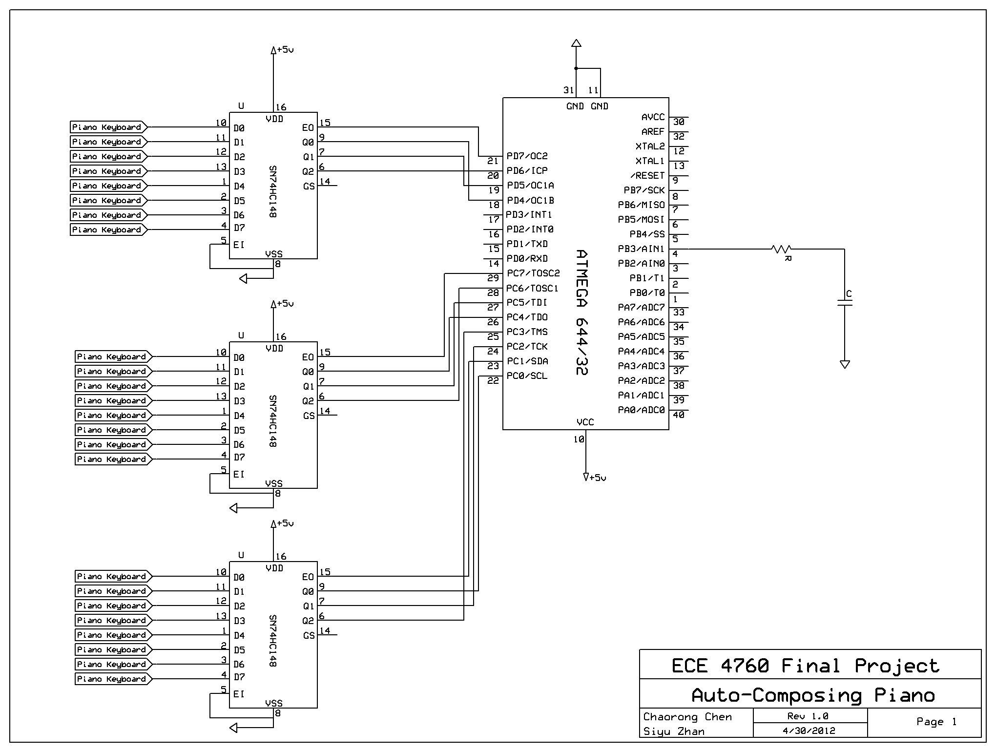
Piano Keyboard Input
The 23 piano keyboard keys are each connected to a wire on the circuit board. To make them to active-low switches that are electrically detectable, we connected the wires to VCC through a 5 kilo-olm resistor. Thus, when the keys are idle, the output voltage is VCC and when keys are pressed, the output voltage approaches zero.
Due to the limited number of input ports on the STK 500, the 23 piano keys from the keyboard cannot be directly connected to the MCU. Instead, they are connected to three 8-3 hardware priority encoders to reduce the number of inputs. The piano keys are divided into three sections, each correspond to seven or eight inputs. Each section is directly connected to its own encoder and produces four encoded outputs: the Enable Output (EO) bit and A0 to A2 encoded bits. The total twelve outputs from the three sections are then connected to the input ports of the STK 500. The software will later decode and debounce the signals to determine which key has been pressed.
The idea of reading piano input via priority encoder is influenced by a previous year’s project (A Keyboard Synthesizer Workstation by Matt Ferrari and Alec Hollingswirth).
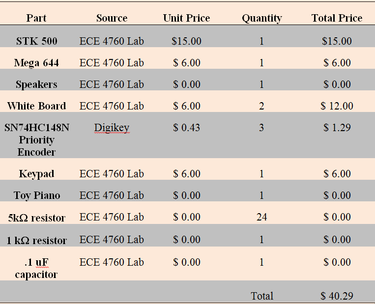
Parts List:
For more detail: Auto-composing keyboard Using Atmega644