Introduction
Digi-Lev
“On the level with digital accuracy.”
The Digi-Lev digital level is a culminating design project for the ECE 476 Microcontrollers course taught by Prof. Bruce Land at the Cornell University department of Electrical and Computer Engineering. Two inventive and industrious students set out to build a position tracking device and one month later became the proud designers of the Digi-Lev digital leveling device. That is our story…read on to find out more about the Digi-Lev, what it does, how it works, and what it can do for you!

We have designed the Digi-Lev to displace the old-fashioned levels used for building and construction with a more accurate, flexible, and full-featured device. The typical level is a piece of measuring equipment consisting of a bubble trapped in liquid to help its user determine if the device is level (perpendicular to the gravitational field). The bouyancy of the bubble will cause it to move off center when the device is tilted. By leveling the device, the bubble comes to rest in the center of two hash marks indicating that the device is indeed level.
Just like a ruler and a scale, the typical level is an analog device and thus subject to error and inconsistency. The user must make a judgement on whether the bubble is indeed centered between the hash marks and the shape of the bubble may vary. Just as the digital caliper and scale have replaced their analog predecessors in applications requiring accuracy and consistency, so comes the Digi-Lev to replace the analog levels of old.
We have designed the Digi-Lev with ease of use in mind. By taking advantage of the computing capabilities of the embedded microcontroller we were able to provide the user many options not available on a typical level while mainting the same intuitive usability. The Digi-Lev works just like a regular level. Place it flush with a surface and it will indicate whether or not the surface is level. It even has a display screen which simulates the bubble of the analog level. A green centred LED lights up to indicate that the device is level. If you stand the level up (perhaps to level a wall as opposed to a floor) the Digi-Lev detects its new orientation and updates the display accordingly. The Digi-Lev also comes equipped with calibration options. The device can be re-calibrated in both of its orientations and the new calibration values can be stored for later use.
So come on and level with us. Level with Digi-Lev.
High Level Design
- Rationale and Sources of our Project Idea
Our project design was originally supposed to be an inertial positioning system. Using the accelerometers to measure acceleration, we had hoped to determine an objects position by integrating, in time, acceleration twice. However, after some time experimenting with amplifying and scaling the accelerometer�s output, we discovered that they were not reliably measuring what we required to do our project. As such, we decided to redesign the project to be a digital level. The rationale behind this was that these accelerometers are quite good at measuring a constant acceleration hence they can be used to accurately determine the presence of gravity. The idea for the project came partly from Professor Land and our own results from experimenting with the accelerometers. - Background Mathematics
According to its data sheet, when 5V Vdd is applied to the accelerometer, approximately 1g of acceleration will result in 0.3V fluctuation from the center (0g = 2.5V) output. When we were trying to do the inertial positioning system, we had built a circuit to amplify and re-center the signal leaving the accelerometer. We found that the circuit worked, but added a bit of noise prohibiting the accuracy we required. When interfacing with the ADC on the microcontroller, we found that we could squeak some accuracy out of it by lowering the Aref from 5.0V to 3.5V. This essentially scales all of the input values and amplifies them as well while not adding any additional noise (the best of both noise). So for example with the Aref at 5.0V the following values emerge from the ADC:Output(0g) = 2.5V ADC(0g) = 512 Output(+/-1g) = 2.2V � 2.8V ADC(+/-1g) = 451 - 573, range = 122
with the Aref at 3.5V the following values emerge from the ADC (note that the +/-1g range is higher resulting more accurate measurement):
Output(0g) = 2.5V
ADC(0g) = 731
Output(+/-1g) = 2.2V � 2.8V
ADC(+/-1g) = 644 � 819, range = 175

- Logical Structure
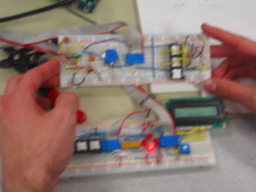
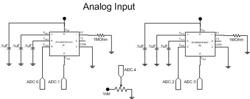
Our design can be basically broken into three blocks: analog input, processing/decision making, and output. The analog input section of our design is quite simple, we interface the accelerometers to the ADC on the MCU. From there the signal is quantized and processed with the software we wrote. The accelerometers have 2-axes each meaning that we have a total of 4-axes of measurement. We mounted the first accelerometer in parallel with the bread-board to measure if the level is placed on a horizontally level surface. The second accelerometer is mounted perpendicularly with the bread-board to measure if the level is placed on a vertically level surface. A potentiometer is also mounted on the board to control a sensitivity reading.This amounts to varying the amount of averaging used in the processing section of the level. The processing/decision portion of the project was all written in software. We average the input coming from the ADC to accurately determine whether the accelerometer is tilted in any direction and the overall orientation of the device. Then we have it calculate approximately how much it is tilted and send this data to the output unit that notifies the user if and by how much the level is tilted. To calibrate the level to a flat surface, there are two buttons on the display board. These buttons are used to calibrate the accelerometers and to write the values to EEPROM. Two calibrations must be performed: one in the horizontal orientation and one in the vertical orientation. The output portion of the level is represented using and LCD and 5 LEDs As can be seen from the schematics in the Appendix section, the LEDs are oriented with a green one in the center and 4 red leds at the N, S, E and W cardinal points. The LEDs do not indicate a magnitude of tilt, they simply detect the presence of it and adjust their display accordingly. To indicate some sort of magnitude, we use the LCD (2×16) to display using a digital equivalent of a conventional level�s bubble. When the bubble is between two hash marks, it is considered to be somewhat level (to determine more accurately the user must refer to the LED readout). Also, the user can select which axis they are viewing on the LCD and what sensitivity has been selected. Finally, the LCD also displays the orientation of the level (either horizontally, or vertically). - Hardware/Software Tradeoffs
In order to obtain a more accurate reading, we wanted to crank up the polling rate of the accelerometers, however, due to the speed of the software, we were unable to do so as we would have liked. This pushed us towards our design of a digital level. High polling rates were not required to obtain a good reading, but we found that they did help. Hence we tried and succeeded in turning up the polling rate by killing the floating point operations we were doing. We worked around this floating point math by cleverly redesigning some decision algorithms. This actually resulted in a much cleaner, more predictable output from the device.
Parts list:
| Device | Model | Qty. | Cost |
| Dual Axis Accelerometer | Analog Devices ADXL202JE | 2 | $10.20 (free samples) |
| 2×16 LCD Module | Varitronix MDLS16264 | 1 | Free (lab equipment) |
| Microcontroller | Atmel ATMega32 | 1 | Free (lab equipment) |
| Development Board | STK500 | 1 | Free (lab equipment) |
| Red LED | Generic | 4 | Free (lab equipment) |
| Green LED | Generic | 1 | Free (lab equipment) |
| Breadboard | Generic | 2 | Free (lab equipment) |
| Pushbuttons | Generic | 3 | Free (lab equipment) |
For more detail: Digi-Level