Summary of Digital Stethoscope Using Atmega644
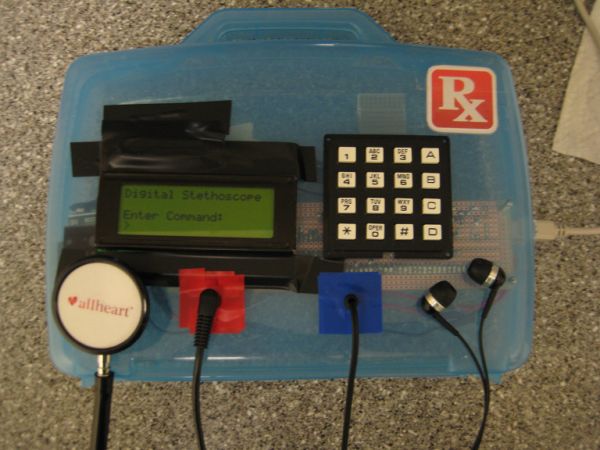
The project "Soundbyte" is a digital stethoscope designed to capture, amplify, play, and record heart sounds in real time for potential cardiac murmur detection. It uses a custom acoustic sensor with an electret condenser microphone, biased and amplified by a circuit, to convert heart sounds into electrical signals sampled at 8 kHz by an ATmega644 microcontroller. The system outputs audio via a 3.5 mm jack, records audio on a 1MB flash memory, and features a keypad and LCD for user interaction. Data can also be visualized and analyzed on a PC via MATLAB, aiding doctors in improved diagnosis.
Parts used in the Soundbyte Project:
- 3.5mm Cable (CP-2206-ND)
- Condenser Microphone (P9955-ND)
- Flash Memory 1MB (W25Q80BVDAIG-ND)
- Operational Amplifier (MCP6231-E/P-ND)
- Stethoscope (AH-DST0201)
- Plastic Box (Clear Blue)
- Max233CPP
- ATmega644 Microcontroller
- Keypad
- Custom PC Board
- Solder board (6 inch)
- Small solder board (2 inch)
- Voltage Regulator (3.3V)
- Resistors (various)
- Capacitors (various)
- Diodes (2 pcs)
- LCD Display (4-line, 20-character wide)
- Switch
- Voltage Regulator (5V)
- 9V Battery
“A digital stethoscope that can amplify, play, and record heart signals in real-time.”
Project Soundbyte
The purpose of this project was to design and implement a digital stethoscope to serve as a platform for potential computer aided diagnosis (CAD) applications for the detection of cardiac murmurs. The system uses a custom-built sensor to capture heart sounds at 8 kHz and converts them to electrical signals to be processed by an ATmega644 microcontroller. The captured signals are outputted via pulse-width modulation to a standard 3.5 mm audio socket for real-time auscultation. In addition, the stethoscope uses a 1MB external Flash memory chip to record and playback audio waveforms. For the user interface, the system includes a 4-line 20-character wide LCD display and a 16-button keypad. Real-time and recorded data can also be visualized using a MATLAB interface that runs on a separate PC and connects to the stethoscope system via the USART interface on the microcontroller. The MATLAB interface also uses the transmitted data to calculate and display the patient’s average heart rate in beats per minute.
This project is meant to provide a framework for developing useful embedded CAD tools for cardiac murmur detection. Heart murmurs may go unnoticed during routine check-ups since detection relies on the training of physicians, the quality of the equipment used, and the severity of the condition. A digital stethoscope can be used to assist physicians in analyzing cardiac signals in real time during auscultation to reduce the risks of not detecting certain conditions.
High Level Design
Overview
The overall architecture of the system is centered on the ATmega644 microcontroller. The acoustic sensor and keypad are inputs to the MCU, while the LCD, headphones, and MATLAB visualization tool are outputs. Communication with the Flash memory is bi-directional.
The MCU runs several software interfaces to support the various features of the digital stethoscope. The signal capturing interface uses the analog-to-digital converter to sample the acoustic sensor at 8 kHz. The real-time audio processing module modifies the measured signal based on user settings and outputs it to the 3.5 mm audio socket via pulse-width modulation. The user interface supports the detection and de-bouncing of keypad button presses as well as controls the LCD display to reflect the current state of the system. In addition, the user interface also outputs real-time or recorded data at 100 Hz to a MATLAB utility running on a separate PC for signal visualization and average heart rate calculations. The Flash interface includes a software library for SPI communication to read from and write data to the external Flash memory chip.
Hardware Design & Implementation
Stethoscope Acoustic Sensor
The stethoscope acoustic sensor was an integral hardware component of the system. The quality of the sensor directly impacts the quality of the real-time audio output as well as all analyses performed on the measured waveforms. Because of this, a custom sensor was designed and developed to capture heart signals. The sensor includes a standard stethoscope chest piece to amplify acoustic signals and an electret condenser microphone to convert the amplified signals to electrical waveforms. A microphone with a 20 Hz – 20 kHz frequency range was selected in order to capture all of the low frequencies characteristic of internal body sounds. The microphone was placed within a rubber tubing as close as possible to the base of the chest piece. In order to reduce noise and improve convenience, a 3.5 mm shielded cable was soldered to the leads of the microphone and pulled through the rubber tubing to interface with the MCU. Figure 3 shows an image of the constructed stethoscope sensor.
The sensor construction was tested by using a multimeter to detect shorts and to verify that proper connections were made. The actual sensing capability of the component was tested using the bias/amplifier circuit described in the next section.
Microphone Bias and Amplifier Circuit
The microphone in the acoustic sensor needed to be biased in order for proper operation. In addition, the output of the microphone is on the order of millivolts, which is relatively small in magnitude compared to the precision of the ADC sampling the sensor (the ADC has a precision of approximately 20 mV when taking 8-bit samples). This makes it challenging for the microcontroller to detect changes in sensor output. In order to address both these issues, a bias and amplifier circuit was designed and implemented to interface the raw sensor output with the MCU. The goal of the circuit was to properly bias the microphone and amplify the sensor output to detect voltage swings caused by sounds. The figure below shows a schematic of the completed circuit.
The typical operating range for the microphone was 2 V, with a maximum rating of 10 V. The MCU provided a voltage of 5 V, so a simple voltage divider circuit with identical 1k resistors was used to reduce the voltage to 2.5 V to bias the microphone. The output of the microphone was passed through a capacitor to remove the DC offset. The capacitor used was large enough to make sure that the desired low frequencies were not filtered out. With two 1k resistors in parallel with the output of the microphone, the equivalent output impedance of the sensor is roughly 400 ohms. Using a 10 uF capacitor, a simple high pass filter with a cutoff frequency around 40 Hz was designed, which is below most of the low frequencies of interest.
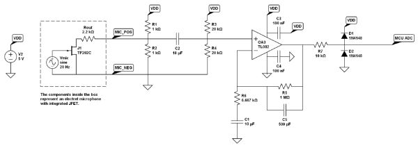
The AC-coupled signal was connected to the positive input (Vin+) of an operational amplifier to boost the signal amplitude. Because the microcontroller ADC measures voltages between 0 and 5 V, the Vin+ line of the op-amp was biased to 2.5 V in order to capture the largest magnitude of positive and negative swings from the microphone output. This biasing was implemented with another voltage divider circuit using identical 20k resistors. The values of these resistors were chosen to be larger than the resistors in the previous voltage divider in order to avoid affecting the equivalent output impedance of the previous stage.
Parts List:
| Component | Part # | Quantity | Vendor | Cost |
|---|---|---|---|---|
| 3.5mm Cable | CP-2206-ND | 1 | Digikey | $3.09 |
| Condenser Microphone | P9955-ND | 1 | Digikey | $2.22 |
| Flash Memory (1 MB) | W25Q80BVDAIG-ND | 1 | Digikey | $1.39 |
| Operational Amplifier | MCP6231-E/P-ND | 1 | Digikey | $0.38 |
| Stethoscope | AH-DST0201 | 1 | Allheart.com | $6.98 |
| Plastic Box (Clear Blue) | N/A | 1 | Michael’s | $3.00 |
| Max233CPP | N/A | 1 | ECE 4760 Lab | $7.00 |
| ATmega644 | N/A | 1 | ECE 4760 Lab | $6.00 |
| Keypad | N/A | 1 | ECE 4760 Lab | $6.00 |
| Custom PC Board | N/A | 1 | ECE 4760 Lab | $4.00 |
| Solder board (6 inch) | N/A | 1 | ECE 4760 Lab | $2.50 |
| Small solder board (2 inch) | N/A | 1 | ECE 4760 Lab | $1.00 |
| Voltage Regulator (3.3V) | N/A | 1 | ECE 4760 Lab | $0.00 |
| Resistors | N/A | Many | ECE 4760 Lab | $0.00 |
| Capacitors | N/A | Many | ECE 4760 Lab | $0.00 |
| Diodes | N/A | 2 | ECE 4760 Lab | $0.00 |
| LCD Display | N/A | 1 | Previously Owned | $0.00 |
| Switch | N/A | 1 | Previously Owned | $0.00 |
| Voltage Regulator (5V) | N/A | 1 | Previously Owned | $0.00 |
| 9V Battery | N/A | 1 | Previously Owned | $0.00 |
| Total: | $43.56 |
For more detail: Digital Stethoscope Using Atmega644