Introduction and Rationale
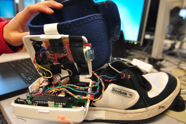
Our ECE 4760 design project integrates three different kinds of sensor measurements to track a user�s movement speed, regularity of gait, force on impact, pronation of foot, as well as other information that may be useful to a podiatrist. We believe there is a need for a cheap metering tool that can be used to log long-term data for later interpretation by a podiatrist.
Rationale and Sources of Inspiration:
During normal walking motion, our feet absorb the shock of impacting the ground by rolling inwards towards the center of the body, distributing weight evenly across the entire foot. Unfortunately, only a quarter of the population are considered “neutral” footed, without any noticable problems with their gait. Half the population suffer from over-pronation, where the feet roll too far inwards causing undue stress to the arch of the foot. The remaining quarter suffer from the opposite problem, supination. Problems associated with incorrect walking form include knee/ankle injuries and foot pain. We hope our project will help podiatrist analyze the problems associated with over-pronation/supination by providing an affordable data measurement/logging device. Using an integrated SD card, each patient would be able to provide weeks worth of data to the podiatrist, capturing the many activities we encounter throughout the day. Treatment and custom othropedics can then be personalized. We imagine our project would also have sports applications, as the data can help improve the form of the user.
Inspiration for this project came from many directions. The original idea was conceived of during a lapse in productivity in a brainstorming session. One group member curiously asked why the outside edge of the other member’s shoe was much more worn out than the inside edge. Wikipedia quickly provided the answer, and soon we had a working proposal. Further motivation came from the fact that the group member suffers from knee pain, one of the highlighted symptoms of supination. Our professor, Bruce Land, supported our idea and provided further ideas that extended off our basic premise.
Sources: http://www.runwashington.com/archive0209/features/brieforthoticsquestion.html
High Level Design
Our project consists of three main functions
- Data Measurement
- Data Processing
- Data Storage/Output
Data Measurement
Our data measurement function primarily replicates the abilities of an inertial measurement unit in a more specified manner. We considered purchasing IMUs directly from Sparkfun, however we decided to save on costs by sampling accelerometers and gyroscopes separately and implementing signal processing in the microcontroller. Since the ATMega644 has eight channels of analog-to-digital converters, we were able to include force-sensitive-resistors (FSRs) to our project. These resistors greatly decrease in resistance when a force is applied to the surface. By placing the sensors in strategic locations, we are able to figure out relative force distributions across the foot. Initially we sampled a digital output gyroscope from Analog Device. We had great difficulties with soldering the tiny packaging to a breakout board, and once it was soldered we could not get the device to interface via SPI. Because we had room in our budget and to save on time, we ordered an analog output gyroscope from Sparkfun because we had already successfully set up multiple ADC readings with the accelerometers and FSRs.
Data Processing
Data processing conducts multiple functions to sense user steps, detect the pronation of a user, log their angular movement of the foot as it moves through the stride, as well as output curves of the user. By using the network of sensors embedded in the shoe, a basic model of how the user moves about can be generated.
Data Storage/Output
We began our design with a simple writing to EEPROM to store data values after shutdown, however we quickly realized that this would not be an acceptable solution since reading from EEPROM requires AVR studio and more importantly, our dataset would be limited to around 2000 values. With a sampling rate of 100 ms, this turns out to be about four minutes worth of values for just one accelerometer. After examining past projects, we decided that an SD card interface would be the best way to store large amounts of data and easily transport it from the shoe to a desktop computer. Once on the computer, the values can be parsed by MATLAB or some other custom program and the dataset can be easily plotted to reveal patterns in the user’s stride.
We also considered using an LCD screen to view the analog outputs and used one during the early testing phases of the project. However, as we began integrating the hardware into the shoe, we relied more upon outputs to Putty via the serial port, and eliminated the LCD display entirely. If we are able to achieve wireless function, we may explore the possibility of sending data wirelessly to a receiver point, and then displaying it via LCD, maybe like a watch.
A wireless RF transmitter and receiver pair was also attempted, but after failed attempts in getting the USART output to sync properly, the wireless portion was scrapped in the interest of time. The original design was to attach a TLP 434 transmitter to the TX pin on the microcontroller while setting up an rf “sniffer” with the receiver feeding its output to an FTDI232R chip which interfacted to a computer via USB. Essentially, the wireless implementation would have almost no overhead compared to the wired version except for the lack of a wire. It was found that wireless noise de-synced the USART communication between the MCU and the FTDI232R chip, so jumbled garbage was received. A brief attempt was made at creating packet headers to ensure reliable transmission, but was halted due to time considerations.
Software Design:
Our software is broken up into three main modules much like our high level design. Final_Project.c/.h, maintains program control flow and data collection. We modularized the signal post processing in calculations.c/.h and SD card functionality in sdcard.c/.h to promote independent parallel development. We have future plans of rewriting the program to be multi-threaded so that all of our monitoring tasks can be simultaneously run and output to a functional GUI. Much of the code for accessing the SD card was adapted from prior ECE 4760 projects. It utilizes the FatFS hardware abstraction layer system, which provides a very intuitive API for handling the specifics of integrating the SD card.
Main Controller
Unlike previous projects, we did not find a need to build a state machine to manage program state. Instead, we set up Timer0 to trigger an ISR every millisecond, which is responsible for managing the timing of several crucial components. It decrements a program counter to trigger the sensor readings every 100 ms. The FatFS specification requires that a time and date stamp be provided to it, which is implemented by a several counters variables that is incremented within the ISR. Additionally, we decrement one additional timer at a rate of 100 Hz to handle the delay timing for the SD card.
Our sensor array utilizes three FSRs, two accelerometers, and one dual-axis gyroscope. All our sensors utilize analog outputs, therefore we utilize seven out of eight ADCs on the ATMega644. To switch between the different channels of the ADC, we assign the 3-bit binary value corresponding to that channel to MUX2:0 bits in the ADMUX. It is important to maintain a logic high in the REFS0 bit of ADMUX throughout the changing of ADMUX. One of our initial problems was ADC output values that were nonsensical because the ADC was referencing the value of the input to some arbitrary AREF, instead of Vcc.
Unlike previous labs, we wanted the full 10-bit resolution of the ATMega644’s ADC. A wrapper function, read_ADC() writes a logic high to the ADSC bit in the ADCSRA to start the conversion. The conversion takes an unspecified amount of time, therefore the only way to ensure proper timing is to trap the execution of the program in a while loop as long as the ADSC bit remains high. Once ADSC goes low, the conversion is finished and both ADCL and ADCH can be read. The datasheet specifies that ADCL must be read before ADCH, otherwise the results of another conversion may erase the values in the register. For simplicity’s sake, we chose to right align our data outputs, meaning the 8 least significant bits of the data will be in ADCL, and the 2 remaining MSB will be in ADCH. Combining the inputs simply requires a logical OR between ADCL and ADCH left shifted by 8 bits.
Rather than write each reading to the SD card at the end of a full set of ADC conversions, we chose to store it in a buffer. Once the buffer is full the program calls the helper functions in the SD card module to write all the values in the buffer to the SD card. Writing to the SD card requires a significant amount of time relative to reading from the ADC values. We chose to have a longer delay, on the order of several seconds, every 100 readings of the ADC rather than having a delay at the end of each ADC read. Using this method, our program requires more data memory, increasing usage by about 30%. If we were close to our budget, we could have opted to use ATMega16 microcontrollers instead, and run the ADC conversions at a slower rate.
Data Monitoring
A debug mode of our device allows the microcontroller to read ADC values from all its devices and print them out in a pretty format for analysis. In a medical application, the shoe can then constantly stream data through USART as strings for post processing on another machine.
Step Detection Processing
While we were collection data, it was discovered that we could implement step detection in multiple ways. Both the FSRs and the accelerometers output consistent enough data that both the falling and rising acceleration or the impact of the foot pressing into the ground and releasing for the next step could be used to detect a step. In our design, we elected to use the accelerometers to implement a three-state state machine to detect and debounce a step. When the ADC value of an accelerometer surpasses a set threshold value, the state machine goes to a “STEPUP” state where it has detected a rising foot and will await for the falling sequence. If the falling sequence does not occur within 0.8 seconds, the state will timeout and return to a waiting, “TRACKING,” state. If a falling acceleration occurs before the timeout and surpasses a falling threshold, then a step is said to have been taken. In field tests, we found that by adjusting the threshold values, we were able to step detect quite well.
Currently, step detection keeps track of the number of steps taken. We could have also multiplied the steps taken by an average stride length to display approximate distance walked.
Pronation Detection
Pronation detection is also done via a state machine, but in this case, we elected to use the force sensors. Pronation detection triggers when the heel FSR force surpasses a set threshhold to signal the heel taking most of the subject’s weight as they roll toward the front of their foot. The state machine then waits a short period for the front sensors to surpass their respective thresholds during a certain timeout window. If a forefoot force is detected, the exact force sensor that fired is located and depending on its physical location, pronation or supination can be determined.
We were originally planning to use our gyroscope to detect the exact degree of rolling that a foot undergoes when makign a step, but conversions and integration of the ADC values from the gyroscope resulted in degree values that drifted linearly. This drift made most of our programming useless, so in the end, the more simplistic FSRs were used.
Writing to SD card
As previously mentioned, our project makes extensive use of the work done by previous ECE 4760 students as well as the FatFS system. In particular, we referenced the following ECE 4760 projects:
Adaptive Alarm Clock
GPS Data Logger
One of the reasons we chose to use SD cards for our data storage was because the interface is accessible via SPI, which is easily implemented with the ATMega644. Essentially, FatFS modularizes all the commands and timing so that the user only needs to worry about setting up the microcontroller with the right SPI configuration. This is done in mmc.c. As per the documentation on the FatFS website, the microcontroller should be set as the master, and the phase and polarity both set to logic low. Within the initialization function of mmc.c, pins B.4(Chip Select), B,5(MOSI), and B.7(SCLK) are set to logic high to designate those pins as output. Fortunately, the two previous groups modified their mmc.c to work with the ATMega664, and we had no difficulties from a software perspective. We did have issues when we first tried to implement the SD card because of hardware problems, which will be discussed in the next section. To set the SD card to communicate via SPI, the following intialization process must be completed:
- Set the SPI clock to 125 kHz
- Wait 80 clock cycles by transmitting a generic SPI command ten times
- Send CMD0 to enter SPI mode in idle mode
- Determine what type of card (SDHC/SD/MMC) by sending the following commmands in order, until one returns a logic high: CMD8, ACMD41, CMD1
- Restore fast clock rate

Writing data to the SD card accessed by calling helper functions provided by FatFS. The file is first opened by calling f_open() passing in the pointer to the FResult object as well as the access type. Writes are done by formatting a string using snprintf and passing the FResult pointer, the formatted string, and the length of the data to be written. FatFS hides the implementation details such as the specific command to send as well as the number of commands (since only eight bits of data can be sent at once through SPI).
Parts List:
| Part | Manufacturer/ Supplier | DigiKey Part Number | Unit Cost | Quantity | Total |
|---|---|---|---|---|---|
| Housing and Ankle brace | – | Previously owned | $0.00 | 1 | $0.00 |
| Shoe | – | Previously owned | $0.00 | 1 | $0.00 |
| SD card breakout board | Sparkfun | – | $10.00 | 1 | $10.00 |
| Adjustable Regulator | Sampled | LT1584 | $0.00 | 1 | $0.00 |
| Accelerometers | Freescale | MMA1260D | $0.00 | 3 | $0.00 |
| Gyroscope | Sparkfun | LPR530AL | $30.00 | 1 | $30.00 |
| Interlink FSRs | Sampled | – | $0.00 | 3 | $0.00 |
| Diodes | ECE 4760 Lab | 1N4001 | $0.00 | 3 | $0.00 |
| Small Solder board | ECE 4760 Lab | – | $2.00 | 3 | $6.00 |
| 9V Battery | ECE 4760 Lab | – | $2.00 | 1 | $2.00 |
| Custom PC Board | ECE 4760 Lab | – | $4.00 | 1 | $4.00 |
| ATMega644 | ECE 4760 Lab | – | $8.00 | 1 | $8.00 |
| DIP sockets | ECE 4760 Lab | – | $0.50 | 1 | $0.50 |
| Header Pins | ECE 4760 Lab | – | $0.05 | 16 | $.80 |
| Misc: Caps/ Resistors/ Regulators | ECE 4760 Lab | – | $0.00 | 1 | $0.00 |
| Total | $68.50 |
For more detail: Embedded Foot Pronation Detection Using Atmega644