Introduction
The goal of this project was to assist the user in learning the proper technique for a physical exercise, in our case a dumbbell bicep curl. As our understanding of biology and anatomy improves, the design of physical exercises is improved by the application of scientific principals and experimental results. For each exercise there is a known pace and kinematic pattern that yields optimal results. In practice however, it is often difficult to follow the prescribed motions. Thus our project was to create a wearable sleeve that coaches the user through the correct motion of a bicep curl. There is significantpotential impact of such a device on the world of bodybuilding or physical rehabilitation, because it will allow people to efficiently train in order to get the most out of their effort, instead of using excessive amounts of weight and poor form. More motivation for this project stems from the high cost of personal trainers who teach proper form and difficulty of maintaining the ideal pace of each exercise. The concept of a haptic exercise coach could fill a niche in the fitness market for self-paced learning ofexercises. Another exciting application is for physical therapy, where such devices could be particularly useful if the functionality was extended to capture and track data on the repetitions and range of motion achieved.
Back to Index
Rationale
The idea behind this project is through the user of sensors to guide a human into performing a bicep curl with the best form possible. The muscle group to be targeted by our device isthe bicep brachii.Our device will be tuned to check the form on one of the many variations on the dumbbell bicep curl.The sources for this idea were from videos seen describing the form of a dumbbell bicep curl on ehow.com, articles on form on bodybuilding.com, and finally details of the physics seen in Kinesiology of exercises from exrx.net. The reason for wanting to create a bicep curl guiding device is that when lifting weights it is important to maintain good form because it allows on to maximize the force being applied to a muscle group. In the case of the bicep curl especially, the form is crucial and frequently done wrong. The challenge with the bicep curl is that there are quite a few ways in which the curl can be performed incorrectly. On top of the large number of ways in which the bicep curl could be performed incorrectly there are also a large number of variations to the bicep curl. The first common mistake is for the person will bring the weight too high and too rapidly, which does not maximize the force on the actual bicep muscle. Bringing the weight past a one hundred degree angle of inclination will reduce the work load on the bicep curl, which defeats the purpose of the bicep curl in the first place. Another error to consider is the rate or pace in which the exercise is performed. If the bicep curl is performed too quickly it does not allow for enough contraction of the bicep muscle to work it appropriately. The next error often made during a bicep curl is that the wrist will change orientation. This change in orientation will cause other muscles, such as the brachiallis, to be used instead. Unless the wrist is oriented close to perpendicular, the force on the bicep brachiiis not maximized.
On top of the range of motion and wrist orientation, the orientation of your elbow is also of great importance. The elbow must remain stationary during the curl, because it is the pivot point on which all the force is applied from the weight in your hand to the bicep brachii muscle group. If the elbow were to move forward the force of the weight being held in your hand is not maximized on the bicep. The force in this case is not maximized because the force of gravity working on the weight is being shifted to reduce the amount of force on the bicep. This elbow movement usually occurs because the weight is too heavy for the maximum load capacity of the bicep muscle. Although intuitively it is best to lift the heaviest weight possible, when it causes poor form it is counter to the point of the exercise. The final errorthat is most often seen in the dumbbell bicep curl exercise is shifting the shoulder. The shoulder often moves up or down during the curl. The major problem with moving the shoulder around is that it shifts the entire apparatus used to perform the bicep curl, which can again reduce the load on the bicep muscle. The counterintuitive nature in this case stems from the use of momentum to move the weight to its maximum location. Another issue that can stem from shoulder motion is that one could shift each shoulder a different amount, which can lead to imbalances between the left and right sides of the body. Imbalance are a big issue because they place strain on your skeletal system and muscle in ways that lead to joint and muscle problems later in life. Imbalance in general should be avoided.
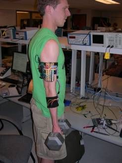
The overall goal of this project is to avoid the potential errors inlifting technique,and therefore maximize force for the best bicep curls. This is a much sought after device for those interested in bodybuilding because it will make the bicep muscle work harder allowing one to achieve a much better pump when they work out. The form correction will take the form of wrist, elbow, and shoulder orientation and position monitoring, which will also prevent muscle size and strength imbalances between the left and right side of the body with consistent form on both sides. Imbalances are not however, addressed to any great extent in this project because the budget would not allow for a sleeve on both arms.The optimization of the exercise will also occur through speed monitoring, which will force the user to have a long, slow contraction of the muscle in the region of largest load on the bicep muscle.
Form and load maximization will be achieved through a feedback system involving accelerometers and vibrator motors. An accelerometer is placed on the lower section of the arm. The purpose of this accelerometer on the wrist is to make sure that the user is notmoving the weight too quickly so that the contraction on the bicep is elongated. Also the accelerometer is going to make sure the user does not go too far past the point of maximum load on the bicep muscle. This accelerometer achieves these goals through feedback that is processed and then sent to three vibrator motors also placed on the lower arm. The vibrator motor on the top of the lower arm will notify the user when the rate of the bicep curl is too much, when the movement is at full extension, and just past the point of load maximization on the bicep muscle.The rate at which the bicep curl is to be performed is checked against a rate of about 1.7 radians per second which is the movement of the weight from full extension to one hundred degrees in just one second. The point defined as just past the point of load maximization is around one hundred to one hundred and ten degrees. The point of maximum load is at ninety degrees where the torque of the weight is maximized because torque is a function of sine.The rate checking of the bicep curl is done through a change in angle calculation in order to maintain a sufficiently low angular velocity. The two vibrator motors on the bottom of the lower arm will notify the user as to whether they are using correct form with respect to their wrists. If the wrist were to deviate in rotation too much in either direction the vibrator motors will go off notifying the user that they are not maximizing the load on the bicep brachii muscle and are using other muscles on the arm, such as the brachialis, instead. The rate and angle calculation are done in the software of the microcontroller. If the rate and angle results deviate too much from the ideal values the vibrator motor corresponding to that deviation will be activated.
The second accelerometer was placed on the upper arm to check the elbow and shoulder movement. This second accelerometer is also paired off with three vibrator motors. Each of these three vibrator motors correspond to a different direction in which the elbow could shift reducing the load maximization on the bicep brachii muscle. The three directions the elbow could move is first the forward direction toward the wrist, which will allow the user to use more momentum to move the weight up and down. The second direction in which the elbow could move is backwards away from the wrist which will reduce the range of motion of the bicep curl as well as the load maximization on the bicep brachii muscle. The final direction the elbow could move is in a sideways direction away from the body of the user. This final direction is the most important because the user is capable of bending the entire lower arm in the opposite direction which use move momentum and circumvent the use of the bicep muscle in order to move the weight up and down. Shifting the elbow in any one of these direction will be kept track of by the software on the microcontroller. In the microcontroller software feedback loop any deviation from the idea value from the accelerometer will result in the activation of the vibrator motor corresponding to the axis/direction of elbow shift.
There were not that many tradeoffs between the software and the hardware that we had to deal with in this project. The first tradeoff we had to deal with was the accuracy of the analog input. In order to get fairly linearly changing value we wanted to average a number of value recorded from the accelerometer which slowed down the software considerably. The averaging of the analog input takes over half the fifty millisecond period that the main loop of the program is allowed for execution. Another hardware/software tradeoff which was eventually worked out, was the eight bit versus the sixteen bit timers. The sixteen bit timer one needed to be set to simulate a fast eight bit timer in order to line up the PWM channel outputs between all six different vibrator motors. If this had not been done the vibrator motors on the PWM channels of timer one would vibrator with significantly less force than the other vibrator motors.
Sources:
Good video on the proper form of dumbbell bicep curl:
http://www.ehow.com/video_2359873_dumbbell-weight-lifting-exercise-beginners.html
Dumbbell bicep curl form description:
http://www.bodybuilding.com/exercises/detail/view/name/dumbbell-bicep-curl
Physics of weight training:
http://www.bodybuilding.com/fun/becker2.htm
How weight lifting has everything to do with physics:
http://www.scoobysworkshop.com/physics.htm
Precise bicep curl form description:
http://www.stumptuous.com/biceps-curl
Kinesiology of a bicep curl:
http://www.exrx.net/Kinesiology/AnglePull.html
Back to Index
Program/Hardware Design
The high level design of the software was to first initialize the microcontroller to setup six different analog inputs, all six pulse width modulator channels, the uart for debugging statements, and enabling the timer zero overflow vector. After the microcontroller components were initialized the timer zero overflow vector continually decrements the variable called the accumulator to zero. The accumulator is set to a high value of twelve which results in a running period of roughly forty nine to fifty micro-seconds which is the time base under which all our calculations are done. While the accumulator is being decremented the program enters its main loop and checks to see if the time based time period is up. If the time base period is up then the program reads in its analog inputs and stores their values as characters in universal variables. The program then execution its feedback control where it checks all the important parameters of the upper arm and the lower arm which are a number of different angles, and speed of exercise execution. Each parameters value is checked against base values that are calculated by from the ideal rates and degrees of freedom we thought were appropriate. Depending on where the analog input value lands the pulse width modulator period is adjusted to cause the corresponding vibrator motor to vibrate at increasingly high speed to indicate how far the user is deviating from the ideal form of the bicep curl.
The overall system architecture of our device is relatively straightforward. As shown in the figure 2 below, there are only two interfaces between the hardware and software, an input and an output. After initializing, the code enters a continuous loop. On each iteration of the loop, the software reads the analog voltages from the accelerometers, then calculates and sets the appropriate motor speeds to provide user feedback. This whole process takes place at 20 Hz, which is fast enough to provide seamless operation from a human viewpoint.
The software was setup similar to that used in the labs for the ece476 class where the correct Mega32 chip was selected and the clock speed was set to 16 MHz.The code was written mainly in C in the CodeVisionAVR IDE.
Included Files:
#include <inttypes.h>
This was included for the purpose of using the printf() function for debugging the code.
#include <avr/io.h>
This was included for input and output enabling for the microcontroller.
#include <avr/interrupt.h>
This was included so that interrupt service routine could be used.
#include <stdio.h>
This was included for the purpose of a few important functions for the purpose of debugging the program.
#include “uart.h”
This was included so that the print output of the function could be place into the hyper terminal.
#include <math.h>
This was included because some math functions, such as atan, were important in the calculation needed for the feedback loop.
Function declaration:
void initialize(void)
This function was used to setup the microcontroller so that all the ports, timers, interrupt service routines, and pulse width modulators.
voidreadAccel(void)
This function was used to read in the all six analog inputs from the accelerometers and average them to be used in calculations used in the feedback loop.
voidmotorControl(void)
This function was used to take the calculations of the necessary parameters of the arm and use them to change the output of the corresponding PWM channel.
To see how the code works in great detail we need to follow the execution of the software. Execution begins at the top of the main function where the initialize function is run. The structure of the initialize function is shown below in figure 3. To start off the initialize function port A is set to an input which is done by setting up the analog input on the port. The analog input is enabled by setting the ADC left adjust result bit to one of the ADMUX register. Also the MUX0 bit of the ADMUX register is set to one to set the gain of the analog input. Next the analog input is enabled by setting the ADEN bit of the ADC control and status register. Also the ADC start conversion bit is set to one to start the analog conversion. After the analog inputs on port A is enabled the uart is enabled so that during testing we could debug the code by reading appropriate parameters to the hyperterminal. A printf statement is then used to show that the program is executing. Next the data direction registers are set for the PWM channel outputs. The pin set to outputs are B.3, B.4, D.6, D.7, D.4, and D.5. Next the prescalars, through timer counter control register B, for timers zero and one are set to four which corresponds to a division of the clock speed by 1024. The timer counter control register for timers one is setup differently here because we need to set the timer to run in fast 8-bit mode. Running in fast 8-bit mode is necessary because the output of the PWM channel would have a different magnitude going with our time base of ~50 ms.The prescalar of timer one is also set to 1024. Next the timer zero overflow interrupt service routine is enabled. The accumulator variables used in the timer zero overflow ISR is initialized and the ISRs are cranked up.
Parts List:
| Description | Qty. |
| BUZ72 | 6 |
| 10k Resistor | 6 |
| TPS7233QP Voltage Regulator | 1 |
| 10 μF Capacitor | 1 |
| 0.1 μF Capacitor | 1 |
| Wire | – |
| Black Thread | – |
| Ribbon Cable | – |
For more detail: Haptic Exercise Coach Using Atmega644