Introduction
For our ECE 476 Final Project, we have built an intelligent, wearable pedometer. This wireless pedometer can calculate many useful statistics such as the number of steps a user has taken, the distance and the speed the person has walked/run, as well as the number of calories the person has burned. This information is wirelessly transmitted to the base-station, and it is displayed on the PC in a useful manner. This project is in collaboration with the Ambumedics Project with John Belina. Traditionally, pedometers only measure the number of steps a user has taken. Recently, more advanced pedometers include GPS units to calculate the distance a person has travelled, but using GPS substantially increase the cost of the product. Our project uses a low-cost accelerometer to determine the distance, speed, number of steps taken, and calories burned of a user instead.
High Level Design
The project will consist of two main components, the wearable sensor and the base-station. The wearable sensor includes an accelerometer, an Atmel Mega 644V microcontroller and an RF transceiver. The base-station will consist of an Atmel Mega 644V, RF transceiver, and MAX233 chip for RS-232 serial communication. The wearable sensor will take the raw data produced by the accelerometer and make determinations on the speed, distance, and number of steps the user has taken. The wearable component will send its interpreted data wirelessly to the base station for aggregating and displaying pertinent data to the user. The following is a high-level block diagram of the system we built.
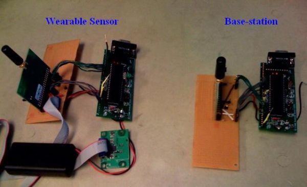
The wearable module is powered from a 3V battery source with two AA batteries in series. The device is tied around the user’s leg, with the accelerometer strapped on the top of the user’s shoe. The calculations on step detection, distance, and speed are done on the wearable sensor, and the result is transmitted wirelessly to the base-station. The result is displayed on the PC through RS232 serial communication with MAX233. The following image shows the actual hardware used
Although the wearable sensor seems bulky and impractical to wear, keep in mind that this is only a prototype. If all components are populated on a single PCB using small packages (DFN or BGA), the size can be significantly reduced. Unfortunately we do not have the budget to fabricate a PCB that costs thousands of dollars for a prototype spin :). For now, the most important aspect is to make the system work with the available resources given to us.
Hardware Design
The two major hardware components in this project are the wearable sensor module and the basestation, which are detailed below. A previous 476 project (Movement of Music) is used as a helpful reference for the hardware design.
Wearable Sensor
The wearable sensor includes the accelerometer, AT Mega644V MCU and the RZ502 wireless module, as illustrated in the block diagram in Figure 1. The following image shows the wearable sensor and its various components.
Tri-Axis Accelerometer
The accelerometer we chose is KXP74 from Kionix. It is a ±2g tri-axis digital accelerometer. This is an ideal part for our application for the following reasons:
- ±2g tri-axis, allows an output range for 19.6m/s^2 acceleration, suitable for a pedometer application
- operating supply voltage (Vdd) from 2.7V to 5.25V, which will work well on a 3V battery supply
- easy-to-use SPI interface with internal ADC, which can communicate directly with ATMega644V
- company based in Ithaca and is supportive of student projects at Cornell University, thank you Kionix for the free samples and support!
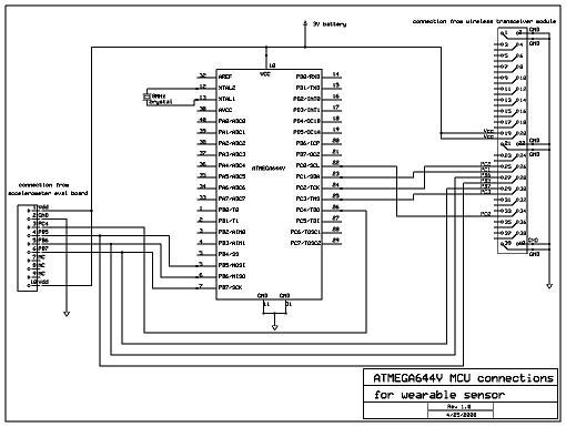
The accelerometer comes in a 5x5x1.2 mm DFN package only, which can make hand soldering fairly stressful. Luckily, Kionix provides free evaluation board (EVAL-74) with a standard 10-pin connector. The following shows the schematic of the evaluation board, and its connection to the AT Mega644V board.
Wireless Transceiver
We have based our wireless design on Andrew Godbehere’s and Nathan Ward’s previous 476 project, which uses Atmel’s 2.4GHz radio transceiver AT86RF230. This wireless chip has several advantages:
- a high baudrate of 250kbps
- low-powered, runs on 3V
- support SPI interface
- 2.4GHz is unlicensed, which does not violate FCC regulations
- in a tiny 44-pad, 7x7x1mm QFN package
However, we wanted to avoid the troubles of hand soldering 32-QFN package. Luckily, the AT86RF230 chip also comes in an Atmel evaluation board (RZ502). Since this is a conjoint project with John Belina’s Amubumedics Project, we are able to borrow two extra RZ502 boards that Amubumedics Group previously owned. The following is the schematic for the RZ502 wireless transceiver board from Atmel’s application note.
Part List
| Part | Part Number | Source | Quantity | Cost ($) | Total |
| ATMega644V | ATMega644/V | Atmel | 2 | Spares from Andrew Godbehere | 0 |
| Tri-Axis digital SPI Accelerometer | KXP74 (eval-74 board) | Kionix | 1 | Sampled | 0 |
| Wireless transceiver and Antenna Module | RZ502 board (AT86RF230 chip) | Atmel | 2 | Previously owned in Ambumedics Project | 0 |
| Bruce Land Prototype Board | NA | ECE 476 Lab | 2 | $5 | 10 |
| MAX233 Serial chip | MAX233 | MAXIM | 1 | Sampled | 0 |
| Solder Board | ECE 476 Lab | 2 | $2.50 | 5 | |
| RS232 connector | ECE 476 Lab | 2 | $1 | 2 | |
| Sip or header socket/plug | ECE 476 Lab | 40 pin | $0.05 | 2 | |
| DIP socket | ECE 476 Lab | 4 | $0.50 | 2 | |
| Various connectors and discrete components | 10 | $0.50 | 5 | ||
| Battery and battery holder | Two AA 1.5V in series | Electronic store | 1 | $5 | 5 |
| Enclosure for the wearable circuitry | Free food box | 0 | |||
| Velco for the enclosure | $3 | 3 | |||
| Total Sum | $31 |
For more detail: Intelligent wireless pedometer