Requirements
- AtMega 16 IC/development board
- 3-Axis accelerometer
- LCD screen 16X2 (for displaying X, Y and Z data)
Description
This project makes use of three out of the eight ADCs present in AtMega16 IC to display the corresponding digital data of X, Y and Z outputs of an accelerometer on 16X2 LCD.
Accelerometer
First let’s talk about the Accelerometer IC; here I have used ADXL-335 which is a 3-axis accelerometer module. This module provides X, Y and Z axis data.
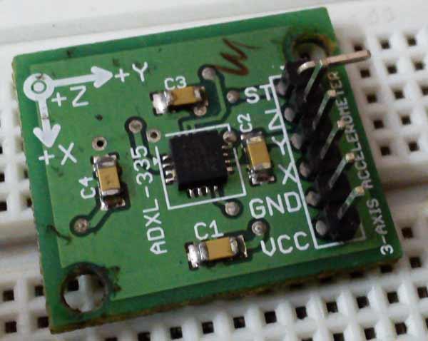
It’s very easy to deal with such kind of modules as they just need the VCC and GND supply to get started, rest it is its job to provide us the analog data.These modules work on simple concept like that of force acting on an object at inclined plane. It deals with the Mg(sin ?) and Mg(cos ?) part of the force and calculate the angle ? for further calculations. Now it also notices the change in force from which acceleration will be calculated.
These accelerometers do not respond to linear movements they respond to accelerated motions at very small scale.
Looking at the above picture you’ll notice that there is a ST pin. This pin deals with the value of ‘g’ (accelerations due to gravity) to be taken while calculating the result. Checkout its data sheet for more information. It will also work on a default value if you do not connect this pin anywhere.
Analog/Digital Converter
Now talking about the ADCs present in AtMega 16; there are 8 independent ADCs which share their pins with that of PORTA. These ADCs are 10 bit which simply means that they can convert a given analog value into its corresponding 10 bit digital data.
Now before moving ahead we should first discuss what ADCs are. ADC stands for Analog to Digital Converter. We all know that microcontrollers work only on digital values, but what if we need to interact it with analog devices or values. In such situations we need a device which can work as communicator between the analog part and digital part. ADCs (analog to digital converter) play the same game; they convert the analog values to digital one by some means of reference (Vref).
In AtMega16, pin 32 requires a reference voltage (normally given +5V) when working with ADCs. Also there’s one more term that’s needed to be introduced: Resolution. In simple terms we can say it’s the precision or accuracy with which an ADC works. For a 10 bit ADC working with 5V Vref. its resolution comes out to be 4.88mV. This further means for every rise or fall of 4.88mV in the analog input the digital output will increase or decrease by one unit, respectively. Since it’s a 10 bit ADC the output data will vary from 0- 1023(2^10=1024) having 1024 different values.
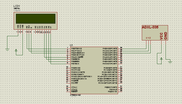
Now coming back to this project, I have connected the X, Y and Z pins to ADC0-ADC2. These provide individual and independent analog values. I have also displayed their corresponding digital outcome on the LCD.
The LCD connections are as follows:
· DATA pins are connected to PB4-PB7, since its working in 4-bit mode
· RS, RW and ES pins are connected to PB0, 1, 2 respectively.
For more detail: Interfacing Triple-Axis Accelerometer with AtMega16