Introduction
Consider you are in a research lab that handles highly hazardous material. You don’t want anybody to enter the room, to even come close to the door. Or consider yourself doing something highly confidential in a room that you would like to know if someone is trying to get in. In all these cases, you might find that a portable security system is useful.
First, having a security system that is able to sense a peson touching the doorknob will give you warning and enough time to react to the visitor, whether or not to allow him/her to enter. Secondly, if the system is able to sense an opening door, even if you accidentally leave the door opened, you may still have enough time to react. Thirdly, you may of course find it useful if the system is able to sense someone or any movements in the room.
Our final project is a portable security system that consists of several sensors with each having a different objective. Each sensor is aimed at detecting some kind of security breach. Most importantly, the entire system is portable, because we make use of two MCUs and wireless RF transmitter / receiver. If the room is huge, appropriate security breach messages can still be communicated from the door to the person inside the room.
Another important note about this project is that the system is easily expendable to accommodate more sensors in order to perform more functionalities. This project is basically built up from several different subsystems with each sensor acting as an integral part of a subsystem. Therefore this project can easily be upgraded in the future to make it more robust and complete.
This project can also be operated in two different modes. One is the online mode (connected to a PC), while the other is the offline mode (not connected to PC). In online mode, the PC is able to act as an administrator to control the functions and to stop the alarm if any of the security subsystem is triggered. In offline mode, the serial connection to PC is disabled and thus the alarm can only be stopped if the correct four digits code are entered into the keypad. Offline mode has limited functionalites compared to online mode.
High Level Design
Our portable security system is able to detect three kinds of security breach:
- Touching a door knob.
- Opening a door.
- Movement in a room.
To complete each objective, we use a different sensor for each task. We built our own capacitance sensor using a touch wire, an operational amplifier, and a few resistors. This capacitance sensor is used to detect a door knob touching. For sensing an opening door, we use an accelerometer. For movement in a room, we use a Passive Infra Red (PIR) sensor.
This project consists of two parts:
- Transmitter Module
- Receiver Module
The transmitter module consists of one MCU (ATMEGA 16L), the capacitance sensor, the accelerometer, and the wireless RF transmitter. The receiver module consists of one MCU (ATMEGA 32), the PIR sensor, and the wireless RF receiver. Because we are making a portable system, we need to transmit the signals from the door (touching doorknob and opening door) from the MCU at the door to the other MCU at the receiver module. Therefore two MCUs and RF transmiter / receiver are needed.
When a person doorknob, a signal will be sent from the capacitance sensor to the MCU on the transmitter. The same happens when someone opens the door, the accelerometer will send a signal to the MCU on the transmitter. The MCU on the transmitter is programmed so that it can handle the two different sensor triggerings appropriately. An RF transmitter is responsible for sending the appropriate message from the transmitter MCU to the receiver MCU stationed next to a computer. At the receiver, the MCU is also programmed such that it can handle the message from the RF transmitter (either from capacitance sensor or from accelerometer). The trasmitting and receiving scheme will be explained in detail in program design section. Furthermore, the receiver MCU is also programmed to handle signals from the PIR sensor, to interface with a keypad, to trigger an alarm, and to interface with the computer to handle the general administrative actions.
The alarm can be controlled by the computer using UART interface. Each sensor triggering will either display an appropriate message to the PC screen or store the log information into an EEPROM memory depending on whether ‘stream’ or ‘save’ or both is activated by the computer. To stop the alarm, you can either use the computer or you have to enter the correct 4 digits code into the keypad. The computer is responsible for setting or changing this 4 digits code, as well as setting the time and date. The computer is also capable of keeping track of the time and date when each of the security system component has been triggered. This can be done by a user by storing the log into the memory. The recorded logs can also be retrieved anytime. Serial connection for the computer can also be disabled. In addition, there is also a clear screen function for the computer.
Standards
The standards for this project are: the transmitter is in compliance with FCC rules concerning Radio Frequency Devices located in Part 15 of Title 47 of the Code of Federal Regulations. We operate the transmitter at a frequency of 433 MHz and transmissions are in bursts less than 10% duty cycle.
This project is created for personal use and educational purpose only; and thus will in no way be commercialized and should not infringe on existing patents, if any.
Hardware Design
When we first came up with this project idea, we searched for capacitance sensor component, but they are all too expensive for this project. Thus we decided to put together our own capacitance sensor, using a relatively simple design that is fairly accurate for our purpose.
The whole idea about the capacitance sensor started when we found out that the voltage on the scope is different when we touch it compared to when nothing is connected. Therefore the circuit for this capacitance sensor is built from this primitive idea using an operational amplifier to amplify the resulting voltage due to the capacitance difference of our body and ground.
The circuits for the transmitter and receiver modules are shown here:
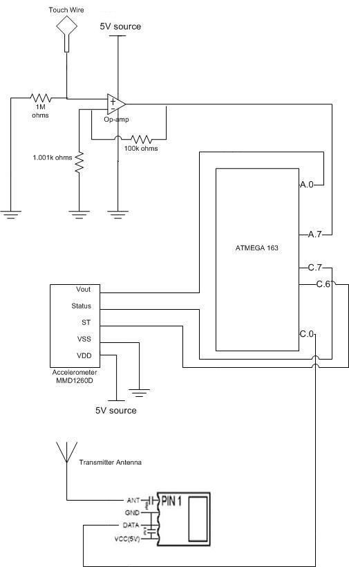
The circuit for the capacitance sensor is the at the top of the left diagram. We use a non-inverting op-amp with a gain of about 100. The touch wire acts as the sensor input and is hooked to the doorknob. It is connected to the positive input of the op-amp. Both inputs are grounded so that the capacitance difference can be sensed each time you touches the wire. This is done in order to saturate the voltage levels to produce a digital high or digital low. The voltage is fed into portA.7 of the MCU. We check the digital signal for a couple times long enough to make sure that the digital voltage level remains the same for a certain period so as to distinguish this touching signal (60Hz – low frequency) from the 433MHz high frequency RF signal.
For sensing an opening door, we used the accelerometer MMD1260D by Freescale Semiconductor. The voltage output of this accelerometer is fed to another channel of A/D converter in the MCU. This accelerometer is able to produce an output voltage that is linearly related to the acceleration within a certain range. But all we need to do is to detect fluctuations from a stable value to detect an opening door.
Pin C.0 is used as an output here to send data to the RF transmitter. We use a simple wire as the transmitter antenna.
For the receiver circuit, the Radiotronix RF receiver is used to receive the signals from the transmitter and they are fed into pin C.7 of the MCU. Another simple wire is used as the antenna.
The Passive Infra Red sensor is obtained from within a commercial product. Its working principle is that the higher the sensed temperature, the lower the output voltage from the PIR sensor. A few resistors and transistor are used to produce a 3V source to drive the PIR sensor and the output voltage from the PIR sensor is fed into pin A.7, an ADC channel of the MCU.
Parts list:
| Index | Item Description | Quantity | Unit Price | Cost |
| 1 | Custom Prototype Board | 2 | $5 | $10 |
| 2 | Atmel MEGA 32 | 1 | $8 | $8 |
| 3 | Atmel MEGA 163 | 1 | $2 | $2 |
| 4 | Battery, 9V | 2 | $2.33 | $4.66 |
| 5 | Transmitter RCT | 1 | $4 | $4 |
| 6 | Receiver RCT | 1 | $4 | $4 |
| 7 | PIR sensor | 1 | $5 | $5 |
| 8 | Accelerometer | 1 | free | $0 |
| 9 | MAX 233 CPP | 1 | free | $0 |
| 10 | MAX 233Connector | 1 | $2 | $2 |
| 11 | Op-amps | from lab | $0 | |
| 12 | Resistors, capacitors, transistors | from lab | $0 | |
| 13 | Keypad | 1 | $5 | $5 |
| Total | $44.66 |
The total cost is under budget with about another $5 to spare.
For more detail: Portable Security System