Introduction
We created a system that takes input from a piano and displays the musical notation for it on a television screen.
The system uses hardware amplification and filtering of a microphone output with code in C compiled on two Atmel Mega644 microcontrollers. The basic tasks required are pitch identification, measurement of note duration, and video generation. We chose this project because both of us play (or have played) musical instruments and know how frustrating it can be to write out sheet music, whether by hand or using a computer program. We felt that this Sheet Music Notator could be a useful tool for beginning musicians and composers.

High Level Description
Rationale and Sources
We wanted to choose a project that could be both useful for a large group of people and rewarding to design and build. As previously mentioned, we are both musicians, so one of the first things that came to mind when we started brainstorming final project ideas was tools for musicians. We were both surprised that such a tool was not already widely used (in fact, we only found one such program on the market, and that, too, after a long search), so we decided to build it.
Logical Structure
We chose to take input from a keyboard specifically because it outputs a synthesized sound and will have clearer frequencies than human-produced sound (though we found that this instrument is actually far from an ideal synthesizer).
The notator consists of the following subsystems: a microphone and preamp stage, a filter stage, a note detection stage, a video driver stage, and then a display stage, arranged as shown in Fig. pi below.
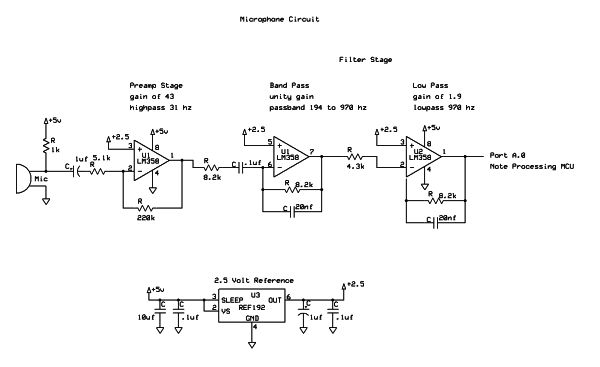
We input the sound from the piano to our system through a microphone. This way, any sound source could theoretically be used with our system, though our program has it tuned for the Casio keyboard we will be using to demo, and calibration for other instruments is outside of the scope of our project. The microphone signal is fed into a preamp stage designed to get the signal to a level that can be read by our ADC. It also has a high pass filter/DC block so that we can center the signal around a frequency of our choice and remove some low frequency noise.
After the preamp stage is a filter stage where all frequency components not in our note range will be filtered out. One of the filter stages also adds gain to give us more resolution. The microphone, preamp, and filter stages are all on one breadboard, called the filtering and amplification board in Fig. pi above. The filtered and amplified signal is read by the ADC of an AtMega644 microcontroller, which detects note pitches and lengths using the note detection methods described in the background math section below. It then sends this information to the video processing MCU using a serial connection.
The video processing MCU takes the length and pitch information for each new note and converts it into a picture drawn onto a black and white television using the NTSC protocol. Notes are correctly displayed on a staff in the sequence they were played. For example, Fig. 2 below shows the output after someone has finished playing “Twinkle,
Background Math
Pitch Determination
A fast Fourier transform (FFT) is used to determine the pitch, or frequency, of each note. A Fourier transform takes a signal that is in the time domain and transforms it to the frequency domain, and an FFT is any algorithm which quickly calculates a discrete Fourier transform, i.e. one in which the input time domain signal and the output frequency domain signal are both discrete.
To take an FFT of continuous time piano music, the FFT algorithm first samples the data to generate the input signal, using the ADC on the microcontroller to get input from the microphone. It takes the real and imaginary components of the signal at discrete time intervals and outputs a one pair of real and imaginary amplitude components corresponding to each sampled frequency. The output frequencies are evenly spaced from 0 to the Nyquist rate (half the sampling rate), so n samples taken at m Hz yields n/2 discrete frequencies starting at 0 and incrementing by 2m/n Hz.
We chose to use a 2 kHz sampling rate with 128 samples for the fft, giving a frequency spacing of 15.625 Hz. Starting at A bellow middle C (A3), notes on a piano are all at least 13 Hz apart, and spacing increases with pitch. The sampling rate set our highest note at A5, which is just below m/2, or 1kHz. With the discrete frequencies for which amplitudes are sampled in this system, no two note frequencies are closest to the same discrete frequency. There is now an injective mapping from piano notes to discrete frequencies from the transform, so every note between A3 and A5 can be detected using this algorithm.
After completing the FFT, we have a vector set of complex amplitudes. Normally, to determine the magnitude of the signal at each frequency, one would take the square root of the sums of the squares of the real and imaginary parts: |H(w)| = sqrt[ (real)^2 + (imaginary)^2]. However, squaring and square rooting are both time-consuming operations, so we simplified the algorithm to only take the sum of the absolute values of the parts: |H(w)| = abs(real) + abs(imaginary). This was appropriate because we were only interested in the frequency with the highest magnitude, and not the actual value of the magnitude.
Length Determination
To determine note length, the program first determines the envelope of the audio signal by first rectifying and then low passing the signal. The filter cutoff is set well below the signal’s lowest frequency component. The sine waves that make up the audio signal will then essentially be averaged so the output after the low pass will be proportional to the amplitude of the audio signal. If the signal isn’t rectified the low pass will average to 0 for any amplitude, but with rectification it will average to about half the amplitude of the sine wave.
Once the envelope has been determined, an algorithm is used to detect when a new note starts. Even with as much low passing as we can afford without excessively attenuating the higher frequencies, the envelope is fairly noisy. Different frequencies have different maximum amplitudes, and a note usually hasn’t decayed completely before the next is played, so a simple threshold or even a simple hysteresis loop won’t work. Figure 3 below shows a shot from the oscilloscope displaying alternating notes, one with a fairly smooth envelope (E3) and one with a very noisy envelope (D4).
The algorithm we implemented detects rising and falling edges. If envelope values are rising, it keeps track of the maximum value since the previous falling edge ended by comparing new to the current maximum value. If a value is above the maximum, it sets the stored maximum to the new value. If it is between the maximum and a threshold somewhat lower than the maximum, the algorithm moves on to the next sample. If the new value is below the threshold, it then considers the signal to be on a falling edge. Falling edges are handled similarly, by checking for a minimum and some amount above the current minimum.
Using this algorithm, the time between two rising edges can be measured to get the note length. We tuned the thresholds by experimenting. If the value is too low, notes will double trigger since the noise will push the envelope beyond the threshold. But, if the threshold value is too high, then the shortest note that registers will be longer, since the time where the decay is less than the threshold will be increased, and if you play a second note before the threshold is crossed it will not register. This algorithm is thus resistant to noise, different max amplitudes for different notes, notes not fully decaying before the next note is played.
Video Generation
This part of the project required only elementary math. Two global position variables are used. The point in the x direction is incremented each time a new note is displayed. The amount of the increment depends on how much space the note displayed takes up. In general, a two-pixel pad is added between each note to make reading easier. The vertical coordinate of a note is always determined relative to the top line of the musical staff. The global y direction pointer is incremented only when one line of music fills up on the screen and we have to move to the screen.
Since the pitch of a note determines the vertical coordinate for the head of the note (see Fig. 4 below for an explanation of the terms “head” and “stem”), a constant value is added to the global y coordinate for each note. Most notes have a stem that extends for 3.5 staff lines above or below the head. The whole note is an exception to this rule, but we treat the whole note as if it has an undrawn stem so that we can always use the same increment of the global y-coordinate to determine the y-coordinate for a pitch. Simple case statements sufficed for this purpose (see Software section and lab5vid.c in Appendix A).
Basic condition checking on the number of pixels used by each line allowed us to move to new lines and new scores as appropriate.
Hardware/Software Tradeoffs
We encountered several tradeoffs when designing are system. The first tradeoff we encountered was cost vs quality in the microphone and in the design in general. The more expensive the microphone the better it would perform so the quicker notes could register and the more accurate the frequency detection would be, but that would also means a more expensive end product. For a consumer device the key would be to find the cheapest microphone that would give you the performance that you desire. For us the microphone we used detected all our picthes correctly nearly 100% of the time so a more expensive microphone wouldn’t have helped in that area, but it would have probably had less noise and as such we could have detected shorter notes. Noise can also be filtered out, but similarly a more robust filter requires more components and would be more expensive.
Parts List:
| Part | Source | Unit Price | Quantity | Total Cost |
|---|---|---|---|---|
| Total | — | — | — | $68.69 |
| Mega644 chip | 4760 Lab | $8.00 | 2 | $16.00 |
| Black and white T.V. | 4760 Lab | $5.00 | 1 | $5.00 |
| Custom PC Board | 4760 Lab | $4.00 | 2 | $8.00 |
| Breadboard | 4760 Lab | $6.00 | 2 | $12.00 |
| 2.5V Reference | Digikey | $3.47 | 2 | $6.94 |
| FT232RL TSSOP Serial-USB Connector | 4760 Lab | $4.00 | 2 | $8.00 |
| DIP socket | Digikey | $0.50 | 2 | $1.00 |
| Casio Keyboard | Previously Owned | $0.00 | 1 | $0.00 |
| Microphone | 4760 Lab | $0.00 | 1 | $0.00 |
| 1-pin jumper cables | 4760 Lab | $1.00 | 8 | $8.00 |
| ISP head pins | 4760 Lab | $0.05 | 75 | $3.75 |
| Wire, Misc. Other Components | 4760 Lab | $0 | — | $0 |
For more detail: Sheet Music Notator Using Atmega644