Introduction:
The purpose of this project was to extend the Mixed Signal AVR simulator written in Fall 02 so that any single-issue microprocessor could be included in the simulation environment rather than limiting the simulations to systems based around ATMEL AT90S8515 series microcontrollers. In order to achieve this goal, a general architectural description language (ADL) simulator was written and the user was provided with abtractions that allow the full specification of a microcontroller model and the corresponding memory hierarchy. Furthermore, the capabilities of the pre-existing simulator were extended to handle multiple microcontrollers at the same time. The final version of the mixed-signal MCU simulator was tested by implementing a 32-bit, single-issue MIPS microprocessor and L1-cache system. The correctness of this model was verified by comparing against a Verilog model of the same processor. In order to verify the operation of the ADL Analog interface of the extended simulator, two instances of the MIPS processor were included in a sinewave-generator and run in parallel. Test results showed that the extended version of the simulator successfully handled two MIPS MCUs running in parallel in a mixed-signal environment.
High Level Design:
The final version of the simulator was written entirely in Java programming language. The code was organized roughly as depicted in the figure below, where each box represents a class and arrows denote the interaction of one class with another. On each arrow, outputs of one type of object that are passed to another object as inputs are shown (eg, the parser passes an array of logic elements to class Logic). For simplicity, only the major classes and the main inputs/outputs of those classes are shown, while a complete listing of the code can be found under the listing section.
Program Organization-
The major difference between the current and the previous versions of the project is that the Hex File Reader has been replaced by the ADLSimulator class.
The ADLSimulator is the superclass of all MCU models and is intended to hide the unnecessary details of cycle-accurate simulation and analog digital interfacing from the user. The ADLSimulator takes the MCU models, the states of the instruction memories at time t=0, and mask files as inputs. It generates instances of the models referenced in the netlist files and loads these models with the proper instructions. The loaded models are passed to the solver class.
Aside form this difference, the solver and the compiler classes were modified significantly to handle general CPU models rather than the hardcoded 8515 model, and further modifications to these files were made to simulate an arbitrary number of CPUs oncurrently. However, the basic working principles of the simulator, the analog-digital interfaces and the algorithms used for analog simulation have remained unchanged.
Results:
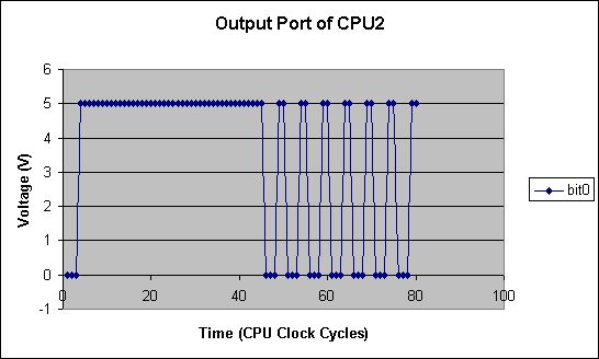
In order to test the operation of the simulator, two MIPS models were run in parallel in a sinewave generator application. The first processor was used to generate the sinewave by performing memory mapped I/O. Memory address 0 was declared as a port in the netlist file, and this PORT was connected to the rest of the analog circuitry as shown below. In order to test correct parallel operation, the second CPU was loaded with instructions that toggle the memory location 0 between 0 and 1. for the second CPU, the least significant bit of memory location 0 was declared as a port and connected to ground through a 1K resistor (not shown). The netlist file that describes the se connections is shown below. The assembly instructions running on the processors is also listed. The corresponding MIPS model is included in the listing section.
The netlist file describing the hardware in the schematics is provided at the right.
The first lines describe an R-2R ladder DAC, followed by the connections to the first
cpu and the logic gates. This is followed by the port declaration for the second cpu.
The dump statements at the end specify the nodes whose values are to be stored into
excel and vcd files for viewing after the simulation. These nodes are also named in the body of
the dump statements to facilitate the viewing process. A more detailed explanation
of the changes to the netlist file format can be found under the netlist files section.
The MIPS assembly instructions running on the two processors are listed below. The code was assembled using the ECE 475 MIPS cross compiler.
For more detail: Signal Microcontroller Simulator using AT90S8515

