Introduction
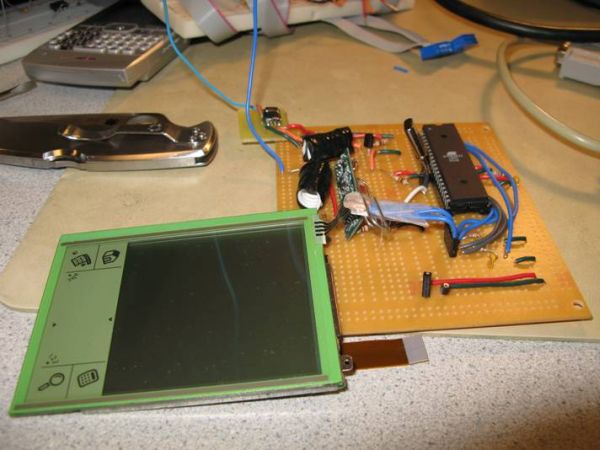
For our final design project, we chose to build a touch screen radio controlled car. Essentially, the RC car will follow a path drawn by the user on the touch screen as it is drawn in real time. Speed and direction of the car was extrapolated from the user drawn path and sent to the car through radio frequency transmission. We utilized a touch screen taken from an old Palm Pilot, the chassis of an old RC car (including the motors), and a transmitter receiver pair. All circuits for both the controller unit and the car were custom built.
We chose this particular project because RC cars are just plain fun, and thus we chose to create something that is essentially a new twist to an old idea. Numerous projects on RC cars have been done throughout the years, but we felt that none of the control schemes were ever intuitive enough to use to absolute beginners. Nothing can be more intuitive than controlling an RC car by drawing the path that you want it to take.
Project overview
The main rationale behind this project was that it seemed to be a fun and interesting idea to implement. Sources of inspiration initially came from previous projects, specifically the numerous RC car projects over the years, as well as the handwriting recognition project from 2006. The handwriting project utilized a touch screen, which gave us the idea to apply the user input tracking capability of the touch screen to an RC car control scheme. However, whereas the handwriting recognition project utilized the touch screen for recognizing drawn patterns, our project would require a greater deal of precision and timing from the screen. We also realized that a user drawn path was a very analog input that would require that the RC car itself have a large number of different turn angles and speeds. The challenge was in writing the algorithm that would effectively extrapolate both speed and direction of the car from the user drawn path in real time, and creating a car that would be capable of following this path.
Background Math
The math involved in extrapolating speed and direction to control the car is essentially nothing more than basic high school geometry. The user input path is quantized into numerous points, which are taken 30 times every second.
The touchpad is quantized into a 190 x 140 grid of points (based entirely on the real life dimensions of the screen itself) and the microcontroller will grab the coordinates of the current location of the user stylus (or nailed finger) 30 times a second. If the user speeds up the stylus, naturally the points will be further spaced apart. It is entirely from this quantization that both speed and direction are calculated.
Speed
Extrapolating speed is a simple matter of calculating the length between each successive point. The longer the distance between successive points, the faster the car should be going. Calculating this distance is a trivial matter of utilizing Pythagoreans Theorem: However, as one can plainly see the points are very close together most of the time, rarely exceeding the distance of 1 to 2 pixels from each other,
his means that the calculated distances are, for the better part of the time, either 0, 1, or 2. This makes extrapolating the speed a little more difficult, and a lot less analog than we would like it to be. Thus we solve this problem by simply averaging the previous 2 distances with the current distance. This gives a much more varied speed calculation,
Direction
Extrapolating the direction from the points requires a bit more math and a lot more creativity. What is most important here are the not the absolute angles derived from the points, but the angle compensation needed by the car with respect to its current position in order to correctly follow the user path. The desired final output is the angle that the cars wheels must turn in order to keep following the path. Of course a car is restricted in the range of angles it can turn, thus all angles greater than a predefined value are declared as invalid inputs.
Once again we have the problem of the points being too close together to extrapolate any real useful data, thus for direction calculations, every group of 15 points are averaged, and the direction calculated from these points. This means that, assuming a sampling frequency of 30 points/second, the direction will only be updated twice a second.
The basic math behind deriving absolute angles between points is simple trigonometry.
The lines that connect each point have been elongated to illustrate the placement of the desired angle. This angle can be easily calculated by first calculating the absolute angle from the line connecting the current point and the previous point with respect to the Y-axis.
Then the previous calculated absolute angle formed by the previous formed line from the past point must be subtracted from this current angle. This final angle will effectively be the angle that the wheels of the car must turn to follow the user defined path.
Embedded within the problem of finding the turn angle lays the problem of detecting when the car needs to move backwards: Below is an example of a user input that would result in the car moving forward, then moving backwards, and then moving forwards again.
The problem at hand is detecting when the change in direction is sharp enough to change the motion of the car from forwards to backwards. It is this acute angle, that any person can obviously see, that must be reliably and efficiently detected through code. Again, we will be exploiting the simple properties of high school geometry to accomplish this task. The Law of Sines dictates that for triangles, an angle is proportional to the length of the side directly opposite to it. Thus this acute angle that is indicative of a change in the movement direction of the car can be quickly extrapolated through the length of sides formed by three points. Below is an illustration of this theory:
The most recent detected point is labeled point 1, and each previous angle is designated as points 2 and 3. As one can plainly see, when moving forward, the length of the line formed between points 1 and 3 will always, without exception exceed the length of both the lines formed between points 1 and 2, and 2 and 3. When moving backwards, the line formed by 1 and 3 will always be shorter than at least one of the other two lines.
The most recent detected point is labeled point 1, and each previous angle is designated as points 2 and 3. As one can plainly see, when moving forward, the length of the line formed between points 1 and 3 will always, without exception exceed the length of both the lines formed between points 1 and 2, and 2 and 3. When moving backwards, the line formed by 1 and 3 will always be shorter than at least one of the other two lines.
Hardware/software Tradeoffs
We realized from the beginning that following a user input path has numerous pitfalls. The most obvious problem lies in the fact that a user input path cannot be exactly translated to RC car movements. The RC car has a very limited range of angles it can turn, and a user input path can very easily exceed the rate of turn for the car. Furthermore, the user can easily move the stylus faster than the car can reasonably follow. Thus, fail safes were programmed into the code that would reject movements that were too fast, or angles too large for the car to follow.
FCC Standards
Our transmitter complies with FCC standards since it does not interfere with licensed transmitters and it transmits in the acceptable range of frequencies found in Part 15 of the FCC rules (http://www.access.gpo.gov/nara/cfr/waisidx_01/47cfr15_01.html). The circuits that we used save power by inverting the transmitted bit stream so that it transmits a 0 when no signal is being transmitted. We do not plan on selling any of our products and we are building less than five of them, so no equipment authorization is required.
Software Design
The software required for this project consisted of two primary code bases: the code on the user side control hardware, and the code needed to properly operate the car. All mathematical calculations for generating speed and direction was performed on the ATMEGA32 controller on the user end, and the controller on the car simply took in wheel angle position and speed through RF, and generated the correct signals for operation.
Touch screen point capturing
Timing was an essential factor in correctly capturing the coordinates for the current stylus position. A new point was taken in every 33.3 milliseconds (30 points/sec), which was assured by regulating this through interrupts. As described above, the touch screen can only output either the X or Y coordinate at any one time, thus input and output must be quickly swapped between the four pins to get both values. The setup that was used in the Handwriting Recognition System project, which required changing pins from input to output, and output to input depending on which coordinate was being read, was used in our code as well, but with heavy modifications. Timing was less of an issue for their project, which relied on recognizing the pattern drawn rather than the absolute positions. However, for our project, we needed to be able to grab these points as quickly as possible. Below is the state machine used to correctly read in the coordinates:
There is a need for a 7 millisecond wait time from switching the port pins to actually reading in the value from the ADC because of the low pass filter. During this time interval the voltage reaches its proper peak value, which can then be properly read in.
Speed and direction calculations
Within the 33.3 millisecond timeframe between successive points, it was necessary to perform all needed calculations for both speed and direction. The math that was involved required very costly operations such as squaring, square roots, and arctangent calculations. The timeframe between each point only allows for approximately 532,800 instructions to be executed, thus shortcuts were taken to minimize the cost of the calculations. A very finite number of values needed to be squared, thus a small array of pre-calculated squared values was placed in FLASH ROM, making a square operation take as long as a simple read from FLASH. This same setup was also done for square root values. Finding a shortcut for arctangent calculations proved a little more difficult, however. Since an arctangent essentially calculates the angle from a slope value, we simply calculated the slope, which required floating point divide operation, and make a rather tediously large If statement that would assign an angle based on the range of the slope value.
Control signal generation for the car
The speed of the car is controlled by changing the duty cycle of the signal that is input to the DC motors. If the car is moving, it has a minimum value of 6/20 and a maximum value of 15/20. This value is directly obtained from the received packet.
The turning direction and degree is controlled by a servo motor. The steering on the RC car was originally controlled by a servo motor that had its own custom controller. We were unable to hack this, so we purchased our own servo and installed it in place of the original. The pulse width is obtained directly from the received packet and ranges from 31 to 65 in units of 1/50000 of a second. The pulse begins every 20 milliseconds. The wheels are straight at a value of 48 and higher values turn right while lower values turn left.
Things tried but failed to work
As stated above, calculating speed and direction for successive points proved to be ineffective due to the fact that these points were more often than not right next to each other. This made calculation of the speed and direction resulting in only a handful of different values. Thus averaging every point with its two previous points to calculate speed, and averaging every 15 points to calculate angle was necessary.

Another huge issue was transmission. The car simply refused to take in the packets sent at a baud rate of 4000. We tried nearly halving the baud rate, using 2400 baud instead, and this fixed the problem. The issue was that the timing was slightly inconsistent between the sent data and received data. Lowering the baud rate allowed for a greater margin of error.
Hardware Design
Designing the hardware proved to be the most tedious and time consuming part of the project. Our project consisted of numerous components that all had to work together to make the design functional. Controlling the two motors on the car chassis required an H-bridge, and controlling the direction of the wheels required a servo. The ATMEGA32 microcontroller itself required certain components, such as a low pass filter for correct ADC operation, and low pass filters were required for ideal operation of the touch screen as well. The circuits for the transmitter and receiver were difficult to construct as well.
Parts List:
| Quantity | Part | Cost |
2 | Mega32 microcontrollers: | $0, sampled from Avnet, Inc. |
1 | RF transmitter and receiver pair: | $0, sampled from Radiotronix |
1 | Radioshack Black Phantom RC car | $0, donated by a friend |
2 | TIP105 and 2 TIP107 transistors: | $0.90 |
1 | Servo motor: | $14.00 |
4 | Optoisolators: | $1.20 |
2 | 40-pin DIP sockets: | $1.00 |
4 | 8-pin DIP sockets: | $0.80 |
2 | Solder boards: | $5.00 |
6 | AA batteries | $5.15 |
Total: $28.50 |
For more detail: Touch Screen Controlled R/C Car Using Atmel Mega32