Introduction
Sound Bite
Our project implements a tuner that continuously outputs the frequency of an input microphone signal with a high degree of accuracy.
Project Summary
This project’s goal is to use a sensitive microphone, computer speakers and a properly designed circuit so that for an input microphone signal a relatively noiseless sinusoidal signal is output to the ADC that is part of the Atmega644 microcontroller. Then with the use of software the correct fundamental frequency from the microphone input may be determined. Because of our interest in music, the tuner was constructed in such a way that it can recognize the frequency of musical notes from A3 (220 Hz) to B5 (987.77 Hz) on the musical scale.
High Level Design
Project Idea Source and Rationale
Despite the various divergent cultures, traditions and languages around the world, the ability to appreciate music seems to be a characteristic present in almost everyone. However though music is thought of as a form of art, musicians spend years perfecting their craft. Proper discipline is appliedwhen regarding pitch, loudness and timbre . The rationale for this project came from Emmanuel whose knowledge of music naturally led to the idea that whistling, singing or playing an instrument off key can be avoided if an accurate tuner is used. Our original goal was to create a tuner that made use of a majority of the knowledge acquired in the ece 476 labs throughout this semester. The original idea was to obtain microphone input from a user attempting to match a note on the musical scale, obtain the pure musical note waveform through the use of Direct Digital Synthesis and a PWM signal, and output both to the black and white TV. The TV would then act similar to an oscilloscope and a user would vary his pitch and intonation in order to cause his own waveform to match the pure note waveform as close as possible. Unfortunately this idea was quickly seen to be implausible as the microphone signal had a significant amount of noise when compared to its PWM generated counterpart. As a result a more practical design that focused on jusr the fundamental frequencies of musical notes was considered.
Background Math
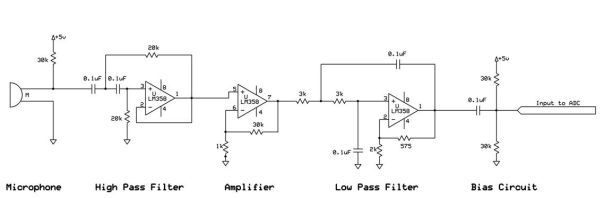
The math involved in this project deals mostly with the use of active filters and amplifiers. A tuner’s function is to determine the fundamental frequency of an input signal. To do so both the 60 Hz noise and the higher frequency harmonics need to be rejected while the desired musical note frquencies need to be passed by a bandpass filter. A simple implementation of second order filters to create the necessary bandpass filter can be performed with the use of the Sallen-Key topology.

The transfer function for this generic circuit may be determined by using Kirchoff’s Current Law twice and rearranging and combining equations. Of more importance is that both a high pass and low pass filter with the Sallen Key topology will have similar transfer functions which result in the same formula for the calculated cutoff frequency of
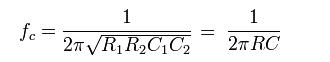
hen the resistors both have the same resistance and the capacitors have the same capacitance. With this formula the various resistor and capacitor values can be determined according to the desired cutoff frequency.
Logical Structure
The high level logical structure of our project is shown below.
The block diagram demonstrates the need for two Atmega644 MCUs for our project. One is used for the conventional data transmission and receiving with the computer terminal (UART) while the other is needed to generate the PWM signal at the correct frequency. A discussion regarding the necessity of two MCUs is performed in the program and hardware design section. The Mega644 on the left uses jumpers between ports to create both a bidirectional command link and a bidirectional data link to its counterpart on the right. Meanwhile the right Mega644 provides the PWM output to the external speakers using the DDS algorithm provided in ece 476 lab 2. The microphone inputs an RF signal into the tuner circuit and after appropriate filtering and amplification the signal is fed into the ADC of the left Mega644 so that the frequency may be calculated using the zero crossing method of finding frequency. The result is displayed using UART in addition to the regular menu options.
Relationship of your design to available IEEE, ISO, ANSI, DIN, and other standards
The relevant standards to our project are those established in 1953 by the International Standardizing Organization regarding the setting of musical note pitches to specific frequencies. Additionally the IEEE Code of Ethics is adhered to during the progress of this project.
Program Design
Program Details
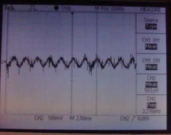
The purpose of our project was to create a tuner that outputs the correct frequency given an RF microphone input. While the hardware ensures that a relatively clean signal will be read into the ADC, the software must take this input and return the frequency of the waveform to the terminal. To do this the ADC digitizes the analog wave. Since the wave will have a bias of 2.5 V (which will be seen in the hardware design) and the ADC runs from 0 to 255 for analog 0V to 5V, the RF signal will oscillate around 2.5 V or a digital sample of 255/2 = 127 which can be considered to be ac ground. So to determine the frequency a count variable tick is used to count the number of zero crossings for several digital samples and then divided by two to find the frequency since one cycle contains two zero crossings. This method is implemented in lab6.c. Additionally implemented in lab6.c was a PWM signal that when passed through a lowpass filter and connected to the external speakers produced a sinusoidal tone at the correct frequency as determined by Direct Digital Synthesis. For our project we want to be able to output using the PWM and receive and determine the frequencies on the musical scale from A3 (220 Hz) to B5 (987.77 Hz). The hardware tuner circuit will guarantee these frequency values will be in the passband. All that the software needs to do is to once again measure the zero crossings. Using a couple of pushbutton and more logic it is possible to increase and decrease the PWM frequency by one semi-note or by a whole octave as long as the range stays between A3 and B5. However adding a menu that is mostly nonblocking results in a change in the measured frequency, most likely a result of timing issues. After more than 30 hrs it was determined that the PWM ISR and the ISR controlling the increment, decrement and calculated frequency were clashing with each other.
A decision was made to move the PWM to a second microcontroller and a bridge from one MCUs port C to its counterparts port C is created with the use of a jumper cable. This is the command link previously mentioned in the logic block diagram where commands for incrementing or decrementing index goes from the left MCU to the right MCU. A diagram of the two MCUs is seen below.
Parts List:
| Part Name | Source | Quantity | Price | Total Item Price |
| Atmega644 MCU | 476 Lab | 2 | $8 | $16 |
| STK | 476 Lab | 2 | $15 | $30 |
| White board | 476 Lab | 2 | $6 | $12 |
| microphone | Friend | 1 | Free | $0 |
| 2 pin flat jumper cables | 476 Lab | 1 | $1 | $1 |
| Power supply | 476 Lab | 2 | $5 | $10 |
| Jumper cables | 476 Lab | 4 | $1 | $4 |
| LM358 amplifier | 476 Lab | 4 | Free | $0 |
| Speakers | 476 Lab | 1 | Free | $0 |
| Total | $73 |
For more detail: Voice Tuner and its Effects Using Atmega32