Summary of 100WATT PV PANEL CONVERTER ATMEGA8 100W DC TO AC ICL7667 ETD34
This project describes a 100W DC to AC inverter for solar PV panels, utilizing an Atmel ATmega8 microcontroller for system control and Maximum Power Point Tracking (MPPT). The circuit integrates a DC-DC boost converter and a DC-AC inverter to step up voltage from the panel to a 350V bus, eventually converting it to 240V AC. Key components include MOSFET drivers, an ETD34 transformer, and specific algorithms to ensure high efficiency above 90% by minimizing power losses in transformers, inductors, and switching elements.
Parts used in the 100Watt PV Panel Converter:
- Atmel ATmega8 microcontroller
- ICL7667 Dual-Power MOSFET Driver
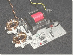
- ETD34 Transformer
- MOSFETs
- DC-DC boost converter
- DC-AC inverter stage
- DC bus capacitor
- PV panel
The use of solar energy will be the topic for a long time an active electronic circuit is used a lot in this business at one of these inverter dc to ac converters. Ac… Electronics Projects, 100Watt PV Panel Converter Atmega8 100W DC to AC ICL7667 ETD34 “atmega8 projects, avr project, microcontroller projects, “
The use of solar energy will be the topic for a long time an active electronic circuit is used a lot in this business at one of these inverter dc to ac converters. Ac dc voltage from PV module circuit (240Vac) is turning 100 watts of power system voltage control provided by Atmel ATmega8. ATmega to drive MOSFETs in the output ICL7667 (Dual-Power MOSFET Driver) The transformer used etd34
All details about the circuit formula’s calculations also pcb circuit diagrams and drawings given ATMega8 software.
Most excellent of all the floors of the circuit given in separate schemas (PV current, voltage sensing, drivers, etc..) You can use this circuit for different applications or projects can be useful in the calculations.
100W SOLAR PANEL INVERTER
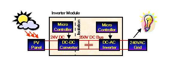
The Inverter Module is designed to connect a 100W PV panel directly to the 240V AC grid. The module consists of a DC-DC boost converter and a DC-AC inverter. The design focus was to totally isolate the DC-DC converter from the DC-AC inverter. The only coupling between the two sides is the DC bus voltage. The AC side regulates the 350V bus by adjusting the average alternating current output from the module. The DC side adjusts the input terminal voltage, to track the Maximum Power Point of the PV panel.
The focus of this thesis was the development of the Half Bridge Dual DC-DC converter stage. As most power loss occurs in the DC boost stage, efficiency was a major design issue. Efficiencies around 95% were aimed for. A micro-controller is used for controlling the converter, and ensuring that maximum power is transferred from the PV panel to the DC bus capacitor. This required the development of a Maximum Power Point Tracking algorithm.
The resulting prototype tracks the maximum power point of the PV panel, and transfers maximum power to the 350V bus with efficiencies above 90%. The major sources of power loss are transformer and inductor core and copper losses, and MOSFET switching and conduction losses. Efficiency was improved by focusing on these areas.
soruce: https://320volt.com/en/atmega8-pv-modul-icin-100w-dc-ac-konvertor-icl7667-etd34/ 100Watt PV Panel Converter Atmega8 100W DC to AC ICL7667 ETD34 alternative link: 100watt-pv-panel-converter-atmega8-100w-dc-to-ac-icl7667-etd34.rar alternative link2 alternative link3
- What is the primary function of the Atmel ATmega8 in this circuit?
The microcontroller controls the converter and ensures maximum power transfer from the PV panel to the DC bus using a Maximum Power Point Tracking algorithm. - How does the inverter module connect to the grid?
The module is designed to connect a 100W PV panel directly to the 240V AC grid. - What is the target efficiency for this design?
The design aimed for efficiencies around 95%, with the resulting prototype achieving above 90%. - Which components are the major sources of power loss?
The major sources of power loss are transformer and inductor core and copper losses, as well as MOSFET switching and conduction losses. - How is the AC side regulated in this system?
The AC side regulates the 350V bus by adjusting the average alternating current output from the module. - Does the DC-DC converter couple directly with the DC-AC inverter?
No, the design focuses on totally isolating the DC-DC converter from the DC-AC inverter, with only the DC bus voltage acting as coupling. - What voltage does the DC side adjust to track the PV panel?
The DC side adjusts the input terminal voltage to track the Maximum Power Point of the PV panel. - Can this circuit be used for different applications?
Yes, the separate schemas for PV current, voltage sensing, and drivers allow the circuit to be useful for different applications or projects.