Summary of 16-key Keypad Decoding with an AVR MCU
This article guides interfacing a 16-key keypad with an AVR microcontroller for reading keypresses. It introduces the 74HC922 decoder IC to save microcontroller I/O pins and explains wiring the keypad directly to the AVR, using pull-down resistors for stable input. The article details using eight I/O pins for the keypad initially and suggests techniques to reduce pin usage. It includes code logic for scanning rows and columns to detect keypresses with debounce handling, suitable for unlocking doors, alarms, or inputting data in embedded projects.
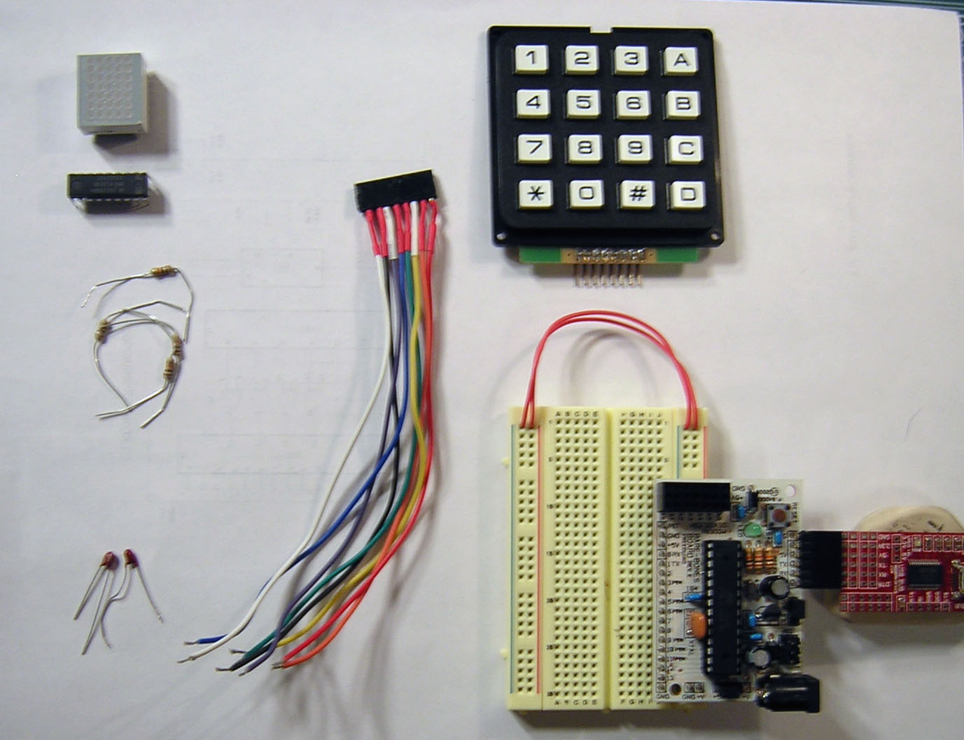
Parts used in the 16-key Keypad AVR Interface Project:
- AVR microcontroller (e.g., ATmega328p)
- AVR programmer
- 16-key keypad
- Solderless breadboard
- Hookup wire
- Soldering iron
- Wire cutters
- 4 x 10k Ohm resistors
- 74HC922 16-key decoder IC (optional)
- 2 x 0.1 µF tantalum capacitors (optional)
- DLO7135 Dot matrix LED (optional)
- 8-pin right-angle male header (optional)
- 8-pin female header (optional)
This instructable will show you how to interface a 16-key keypad to your AVR microcontroller and read the key when a key is pressed. I’ll introduce the keypad first, then the 74HC922 16-key decoder IC as a pin-saving mechanism, then finally how to take the data and massage it so that you get the correct number for the keypress.
A 16-key keypad can be a useful addition to any embedded project, possibly acting as a code input device for opening a door or as a general input to any project requiring the input of multiple values, like alarm circuits, games, puzzles, DTMF generators.
Step 1: Equipment List
This instructable doesn’t have (m)any expensive components if you already have an AVR setup. You can buy everything online, although I’ve found if you check your local electronic warehouse/shop (if you have one) you will be able to pick up everything considerably cheaper, though.
You’ll need the following:
- AVR microcontroller and a programmer. Arduino, Bare Bones Kit, Freeduino, Boarduino, and all the other clones work just fine. Of course, your custom own ghetto setup will suffice too. Just for the record, the firmware was written for an ATmega328p, so it should run well on that class of AVR’s and probably many others with little to no modification.
- Something to compile your code.
- A 16-key keypad. The leading outlets carry them but they can tend to be spendy, so maybe try Jameco.com or do a search for “16-key keypad” on google. It shouldn’t run you more than $6-7
- Solderless breadboard
- hookupwire, soldering iron, wire cutters, etc
- 4 10k resistors
Optional
These parts aren’t necessary for you to figure out how it works, but this instructable shows several different ways to connect this keypad and read data from it, so depending on the parts you want to do, you may or may not need the following.
- 74C922 IC. This is a 16-key encoder. You can pick them up from mouser.com or digikey.com for around $5. I got a handful at my local electronics shop for $0.95 each.
- 2 x 0.1 uF tantalum capacitors. You can probably get away with ceramic if you have them already.
- DLO7135 Dot matrix LED. This is one SWEEET component. They sell for over $10-15 each online, but, again, I picked up 10 of these at my local electronics shop for $1.50 each.
- 8 pin right-angle header and matching female header for the keypad
I think that’s about it. Let’s get building!
Step 2: Wire up your keypad
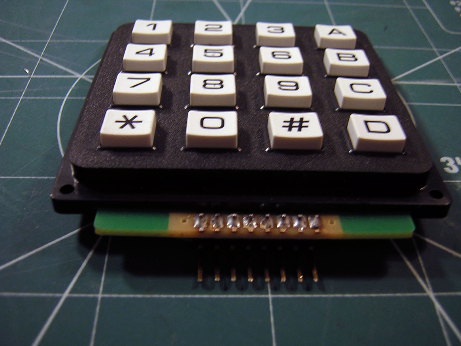
Take your keypad an examine the bottom aspect for soldering pads. My keypad came in a package with hardly any information. Definitely no insert, just some markings on the cardboard outer part that described how the pins matched to columns. Well, that’s really all we need, isn’t it?
I first started by breaking an 8-piece section from a long male right angle breakaway header that I always like to keep lying around. This is totally optional. You can solder your wires directly to the pads if that suits you. The pictures below show the header soldered on.
If you soldered your wires directly to the board then you don’t have to worry about making a cable for it. If you did attach a header, then mate it with the female 8-pin header (again, I just snipped off the right section from a long piece I had around). Solder your wires to it, maybe throw on some shrink tubing and call that part a day. Because I am a bone head and constantly worried that I’ll hook up the wrong wires, i chose hookup wire of different colors and used the mnemonic for the visible spectrum ROYGBIV to choose my wire color from pin 1 to pin 8. I need help.
Got your keypad setup? Good, we’ll connect it to our microcontroller and start reading keypresses.
Step 3: Reading Keypresses on AVR
Ok, first thing you’ll notice is that we’re going to be sucking up 8 I/O ports for this bloody keypad. That’s a lot of I/O. In the next steps I’ll show you how you can reduce that to around four, maybe a couple more depending on how much control you want. But for now, we’re going to hook this sucker right into eight free I/O ports of our AVR.
I chose PD[2..7] and PB[0..1] for my connections. Shy away from PD[0..1] if you want to use serial communication on your arduino or other clone. I also had problems with my pins floating, so i used four 10k resistors to pull down the column pins to ground. Your AVR probably has internal pull-ups, but the logic I had already come up with in my head didn’t work well with that. You’ll note that there’s no pin or hookup for power to the keypad, unlike the binary thumbwheel switch I talked about in a previous instructable.
Here’s the basic idea. Pull the four column pins down to 0V. Set those pins as input. Set your row pins as output with initial logic 0 values. Loop through each row, sending a logic 1 to the row and read the column pins. If there is a one in there, then you have a keypress. Also of note is the issue of key debounce. Through experimentation I found a workable delay rate, otherwise you’ll get many many keypress notifications for each single keypress. Depending on the speed of your MCU, you may have to tweek it a little, too.
I’ve attached a file at the bottom that I wrote for this section to demonstrate direct connection and reading of the keypad. If you choose to use it you will have to modify it as I reference libraries that I wrote for serial communication. Other than that, I think it should be generally fine. Here’s pseudo code to show the flow:
ROWS set INPUT COLS set OUTPUT for (ever) { for each ROW from 0 to 3 { Set ROW HIGH if COL1 HIGH number pressed is ( 4 * ROW) else if COL2 HIGH number pressed is ( (4 * ROW) + 1) if COL3 HIGH number pressed is ( 4 * ROW) + 3) if COL4 HIGH number pressed is ( (4 * ROW) + 3) delay for debounce Set ROW LOW } }
N.B. The numbers are their logical numbers from 0 to 15, not the actual number on the key that was pressed. To do this, you need to either add more logic in your “number pressed is …” section, or map it to an array, which is just a couple of steps away. First, let’s see how to reduce the number of I/O pins this keypad is taking on our microcontroller.
For more details, click: 16-key Keypad Decoding with an AVR MCU


