Summary of 3-20V 01-10A POWER SUPPLY CIRCUIT ATMEGA8 LCD AMMETER, VOLTMETER
Summary: The article explains how to convert an AT/ATX computer power supply into an adjustable lab-style 3–20.5 V, 0.1–10 A bench supply using an ATMega8-based monitoring board. It covers required PSU modifications (removing unused rails, replacing capacitors, disabling feedback/protections), shunt and multi-turn potentiometer choices, PCB details, setup and calibration steps, safe initial power-up, practical uses (battery charging, screwdriver), and cautions about differing PSU designs and ADC resolution limits.
Parts used in the 3-20.5V 0.1-10A Power Supply Project:
- AT or ATX computer power supply (e.g., CODEGEN 300W or CHIEFTEC 350W)
- ATMega8 microcontroller board with ADC and firmware
- Replacement electrolytic capacitors rated 25–35V for the 12V channel
- Diode assembly for the 12V channel
- Output filter chokes
- Shunt resistor (from a Chinese tester)
- Multiturning potentiometers BOURNS 3590 series
- Multiturning trimming potentiometers BOURNS 3266 or BOURNS 3296
- Single-sided PCB (145 x 75 mm) for the monitoring/control board
- SMD fuse or jumper pads on the PCB
- Mounting bolts to attach the PCB to the PSU wall
- 60W incandescent lamp (for safe initial power-up)
- Indicator/display module (to show voltage/current and arrows)
![]() What cannot do more than one radio amateur? What can not be more than one radio amateur? That’s right – without a GOOD power supply, or even better, a GOOD TWO-CHANNEL power supply. That’s right – without a GOOD power supply, or even better, a GOOD TWO-CHANNEL power supply. In this article I will describe how you can make a good, in my opinion, power supply from a conventional computer (AT or ATX). In my opinion, it is a good idea to use a conventional computer (AT or ATX). The idea is good because you don’t need to buy expensive transformers, transistors, wind pulse transformers, and coils … We have an average ATX 300W power supply in the city on the radio market at 45-50 UAH (~ $ 10). It is a good idea to buy expensive transformers, coil, transistors, wind pulse transformers and coils … 45-50 UAH ($ 10). Naturally, this is for used. Naturally, this is for used. Immediately it is worth making a reservation that the higher the quality of the power supply from which you alter, then you can get the best performance from the finished power supply. It is worth it that you can get it. This is due to the fact that in the “Chinese” PSU there may be absolutely no filters at the input, and almost all the filters at the output! It can be used for the PSU. Therefore, it is recommended to look at the “victim”. Therefore, it is recommended to look at the “victim”. I myself made a power supply from the old CODEGEN 300W. I myself made a power supply from the old CODEGEN 300W. Although not ideal of course, but you can live. Although not ideal of course, but you can live. Made to order from CHIEFTEC 350W. Made to order from CHIEFTEC 350W. This is almost ideal – filters at the input, filters (and even some !!!) at the output, well, etc. This is almost ideal – filters for input, filters (and even some !!!) for output, well, etc.
What cannot do more than one radio amateur? What can not be more than one radio amateur? That’s right – without a GOOD power supply, or even better, a GOOD TWO-CHANNEL power supply. That’s right – without a GOOD power supply, or even better, a GOOD TWO-CHANNEL power supply. In this article I will describe how you can make a good, in my opinion, power supply from a conventional computer (AT or ATX). In my opinion, it is a good idea to use a conventional computer (AT or ATX). The idea is good because you don’t need to buy expensive transformers, transistors, wind pulse transformers, and coils … We have an average ATX 300W power supply in the city on the radio market at 45-50 UAH (~ $ 10). It is a good idea to buy expensive transformers, coil, transistors, wind pulse transformers and coils … 45-50 UAH ($ 10). Naturally, this is for used. Naturally, this is for used. Immediately it is worth making a reservation that the higher the quality of the power supply from which you alter, then you can get the best performance from the finished power supply. It is worth it that you can get it. This is due to the fact that in the “Chinese” PSU there may be absolutely no filters at the input, and almost all the filters at the output! It can be used for the PSU. Therefore, it is recommended to look at the “victim”. Therefore, it is recommended to look at the “victim”. I myself made a power supply from the old CODEGEN 300W. I myself made a power supply from the old CODEGEN 300W. Although not ideal of course, but you can live. Although not ideal of course, but you can live. Made to order from CHIEFTEC 350W. Made to order from CHIEFTEC 350W. This is almost ideal – filters at the input, filters (and even some !!!) at the output, well, etc. This is almost ideal – filters for input, filters (and even some !!!) for output, well, etc.
-
- Voltage – 3 – 20.5 Volts
- Current – 0.1 – 10A
- Pulsations – depends on the model “source”.
In the manufacture of such a power supply there is one “BUT”: if you have not repaired it at once or at least did not disassemble the computer power supply, then it will be problematic to make a laboratory one. This is due to the fact that there are a lot of schematic solutions for computer power supplies and I cannot describe all the necessary modifications. In secret I will say that I burned 2 BP before I got what I wanted. In this article, I will describe how to make a board for monitoring voltage and current, where to connect it, and what to do in the power supply itself, but I will not give you an exact rework scheme. I can only tell you where to get the circuit for your BP.
Well, and so on. I think the first link will help the most. One more “but”: the circuit is designed for use in a power supply unit based on a fairly common PWM chip – TL494 (analogs KA7500, MW7575, mPC494C, IR3M02, M1114EU). Maybe it can be screwed to others, but I have not tried this.
The idea was taken from the magazine “Radio 2004/10” p. 33-34. But there the measuring circuit was implemented on KR572PV2A and LED indicators, one measured value was displayed (current or voltage). It is worth reading the article – there are many interesting things about reworking the BP described, but I did not repeat the scheme. I took the controller with the ADC and rushed ….
Scheme. (01/23/2009 a corrected version of the circuit is posted, which corresponds to a printed circuit board and firmware.)

Schemetic
A little explanation of the scheme. In the dotted line circled part of the scheme, which is located on the power supply board. There are elements that need to be put instead of what is there. Do not touch the rest of the TL494 harness.
As a voltage source, we use a channel of 12 volts, which is slightly altered. Alteration consists in replacing ALL capacitors in a 12-volt circuit with capacitors of the same (or more) capacity, but with a higher voltage of 25-35 volts. Channel 5 Volt, I generally threw out – dropped the diode assembly and all the elements, except for the common choke. The -12V channel also needs to be redone for more voltage – we will also use it. Channel 3.3 Volts also need to be removed so that it does not bother us.
In general, ideally, you need to leave only the diode assembly of the 12 Volt channel and the capacitors / chokes of the filter of this channel. It is also necessary to remove the feedback circuit for voltage and current. If the OC circuit is not hard to find by voltage – usually on 1 pin TL494, then by current (short circuit protection) you usually have to search for a rather long time, especially if there is no circuit. Sometimes it is an OS for 15-16 output of the same PWM, and sometimes a tricky connection from the midpoint of the control transformer. But these chains need to be removed and make sure that nothing blocks the operation of our BP. Otherwise, the laboratory will not work. For example – in CODEGEN, I forgot to remove the OS by current … And I could not raise the voltage above 14 Volt – the protection for the current and the power supply cut off completely. Another important note:
It is necessary to isolate the PSU case from all internal circuits. This is due to the fact that on the PSU case there is a common wire. If, quite by chance, to touch the “+” exit to the case, then a good firework turns out. Since now there is no protection against short-circuit, and there is only a current limit, but it is implemented by a negative conclusion. That is how I burned the first model of my BP.
To measure the current taken shunt from the Chinese tester. “Constantan wires”, as in “Radio” I did not find, because I do not know what it is. And in the Chinese tester just the right thickness, and length! Multiturnal resistors BOURNS 3590s are used as regulators. Although you can put the usual, but the accuracy of setting the voltage and current did not please me. Multiturning trimmers from the same company were used as trimming resistors: BOURNS 3266 or BOURNS 3296 .
Printed circuit board.
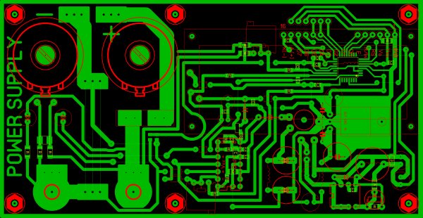
Printed circuit board
One-sided printed circuit board size 145 * 75 mm. Mounted with bolts directly on the wall of the PSU. On the left side of the jumper, the location of the shunt installation is indicated.
Attention! On the board there are two tricky jumpers – under the fuse 2 SMD jumpers – you need to solder ONLY ONLY – the right one is best. In attachments you can download the board in the format Sprint-Layout 5.0
We collect.
Here is what it looks like when assembled:
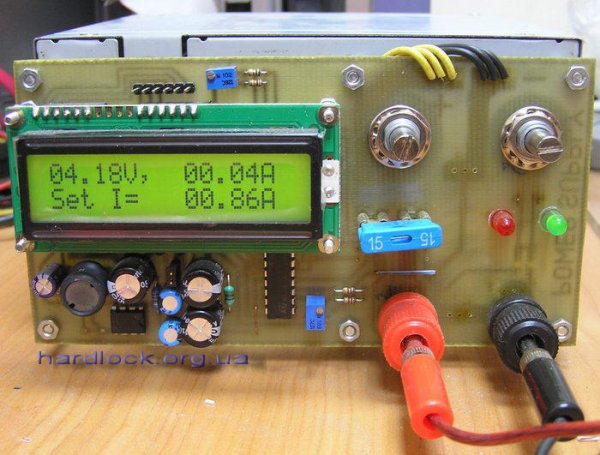
The right variable resistor sets the required voltage, the left – the current. Please note that the set current is also displayed on the indicator (Set I = 00.86A).
A little about setting up the measuring part.
After assembly, it is recommended to turn on the power supply through a 60W incandescent lamp. This will avoid fireworks.
If everything worked and did not explode, then you can proceed to the setting (after turning on the power supply without a lamp), which comes down to adjusting the trimming resistors in the current and voltage measuring circuit. So the voltage at the output of the BP = 20 Volts should correspond to a voltage of 2.5 Volts on the average output of the resistor ” Measurement” U ” ” – the 23rd output of the controller. Also with the current. 10A corresponds to a voltage of 2.5 V at the average output of the ” Gain” I ” resistor – the 24th output of the controller. You can simply connect the exact power devices to the output of the power supply unit and, by measuring the voltage, adjust the ” Measurement” U ” ” as necessary. Similarly, the current can be adjusted using a reference ammeter.
With this power supply, it is very convenient to charge any batteries. For example, to charge a lead 12V / 7A / h battery, set the voltage = 14.2 V, current = 0.7 – 1.5 A (according to the instructions for the battery). Connect the battery to the power supply, and if the charge current is greater than the set, it will be limited (this will drop the voltage). The indicator at this time will display the symbol ” ↓ ” (example Set I = 00.86A ↓ ) and the red LED will light up. When the current drops to the set value or below, the voltage will be limited. (At the same time, the LED and the symbol ” ↓ ” go out). Thus, the battery is charged at first with a stable current, and at the end of the charge – with a stable voltage.
From this power supply unit, I charged lithium batteries from mobile phones (I sometimes forget to charge the house, and not only me), a camera. In the photo, I just finished charging the battery from the phone. Lead batteries from UPS (in another application) 6B and 12V. I even had to charge the battery once in my car. I put 14.4 volts, 10A and during the night the battery was charged, and my power supply was tested.
Also, the power supply unit was used to power the 18-volt screwdriver. The current at the start was limited to 8 amps (specially), but it didn’t interfere with the drilling and tightening of screws (4.5 * 85 mm) – it was just a smoother start. In general, there are many applications of this BP.
At the beginning of the article, I mentioned a TWO-CHANNEL POWER SUPPLY. So – no one forbids to collect two such power supply and put them together. In this case, you can turn them on in series and get up to 40 volts !!! I do not recommend parallel inclusion.
Well, in the end I will add a spoonful of tar. The ATMega8 is not a very high-quality ADC (only 10 bits), so the readings on the indicator all the time jump a little (last bit), but I doubt that you can achieve the best without using an external ADC or splitting the measurement range into several subranges. But it is already more difficult … I also want to add that the PCB does not interfere with the remake – to separate the analog and digital power, dissolve the earth according to the mind, and so on.
- What voltages and current ranges does the modified power supply provide?
Voltage 3–20.5 V and current 0.1–10 A as specified in the article. - Can I use any ATX/AT power supply for this project?
Yes, but the article warns that higher quality PSUs with input/output filters give better results and some PSUs require different rework due to varied designs. - What modifications are needed on the 12V channel?
Replace all capacitors in the 12V circuit with equal or higher capacitance rated 25–35 V and retain the diode assembly and filter components. - Do I need to remove other rails like 5V, 3.3V, and -12V?
Yes; remove the 5 V and 3.3 V channels and rework -12 V for higher voltage so they do not interfere, leaving mainly the 12 V diode assembly and filters. - How is current measured in this design?
Current is measured using a shunt resistor salvaged from a Chinese tester, with the ATMega8 reading the voltage across it. - How should I perform the first power-up safely?
Power the supply through a 60 W incandescent lamp to prevent damage in case of faults. - How are voltage and current calibration targets related to controller pins?
Set 20 V output to correspond to 2.5 V at the Measurement U output (controller pin 23) and 10 A to 2.5 V at the Gain I output (controller pin 24) as described. - Can two of these supplies be combined for higher voltage?
Yes, two supplies can be connected in series to obtain up to about 40 V; parallel connection is not recommended. - Is the ATMega8 ADC ideal for precise readings?
No, ATMega8 has a 10-bit ADC so readings may jitter slightly and are not as precise as a higher-resolution external ADC. - What practical uses are mentioned for the finished supply?
Charging lead and lithium batteries, powering an 18 V screwdriver with limited start current, and general bench power needs.