Introduction
Our project is a 3-dimensional game control for a video game displayed on a black and white television set.
Motivation and Overview
In the recent push in technology, many new computer and game interfaces have been created, many of which include wireless control. Our unit is a novel method for 3-dimensional control. The interface we have designed for this project has many other possible applications other than video game control. This may include 3-dimensional drawing or animation. For instance, instead of using a scroll mouse to zoom into and out of an image, it would be possible using 3-dimensional control to simply draw all of the dimensions of the figure out in air without zooming. Because of the limited time available to complete this project, however, we have written a video game to demonstrate how our interface functions and how it may be used.
The project is to realize a user-friendly control, in which the user simply grabs a ball and moves it in a three-dimensional space. The exact coordinates of the position of the ball are then calculated and outputted onto video using a 3-D to 2-D projection method that we have developed.
High Level Design
The three-dimensional video game project was inspired by a desire to
utilize sensors which track in three dimensions. Several recent technologies may serve as inspiration. In particular, the hugely popular Wii gaming system uses motions in all three dimensions for play. While the Wii served as inspiration, our interface is an original concept and more closely resembles a three-dimensional take with non-wireless sensing hardware because of hardware limitations.
The Concept
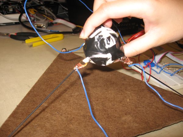
The controller consists of a ping-pong ball mounted in the center of a triangular board by three stretch sensors. The user controls the game by holding the ping-pong ball and moving it in the space above the board as desired to control the video game. We use a 3-D to 2-D projection method that directly maps the position of the ping pong ball to a position on the screen. The geometry of the board is shown in the appendix.
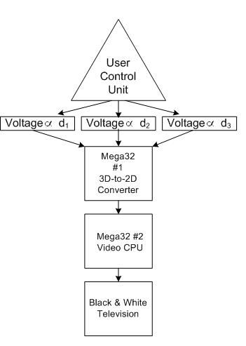
The output from the control unit is converted to 2D coordinates, which are used to generate video code displayed on a black and white TV. The overall data-path for the system is shown below.
Background Mathematics
The calculations used to compute our 3D to 2D projection were based on several known parameters and equations expressing the board’s geometric properties. The equations, and our setup are as follows, a diagram showing the correspondence of the variable to the board is available in the appendix:

From these equations, with only x, y, and z being unknown, it was possible to use Mathematica to solve this system. The resulting equations are used to calculate the absolute positions of our coordinate system (given z2 and z3 are both zero):

Hardware-Software Balance
Implementing this data-path successfully requires a delicate combination of hardware and software. The two important functions of the software are (1) to calculate the 3D coordinate position using the data from the control unit and project it to two dimensions, and (2) to generate the video code. The main hardware components are the control unit, two Mega32 CPUs, and a black and white TV. Because one Mega32 CPU cannot carry out both functions mentioned above within one frame refresh of the tv, we have used two CPUs in the project. One Mega32 CPU is dedicated for 3-dimensional coordinate detection and 3D-to-2D projection. The resultant 2D coordinate data is transmitted to the second Mega32 CPU. The second CPU, in turn, plots the video game output to the black-and-white TV.
Standards and Trademarks
IEEE standards are not relevant to our project because we have no wireless components.
Hardware Design
The game controller is an essential hardware aspect for this project. The controller design was entirely original. The sensors used for position dectection are strech sensors whose resistances change as they are stretched (stretch sensor). The controller base is an equilateral triangle built from hardboard. A 4-inch length of stretch sensor is bolted to each corner of the triangle and tied to Vcc rail of the Mega32. The other end of the stretch sensors are each tied to one end of a 3-kΩ resistor and secured to a ping-pong ball. The other ends of the resistors are connected to the MCU ground rail. The voltages across the 3-kΩ resistors are fed into the A/D input of the MCU. The combination of the stretch sensors and resistors creates three voltage dividers. The voltages read at the A/D input of the MCU increases when the stretch sensor is less stretched, As a result, the voltage across the 3-kΩ resistors become higher. The sensors are sized to have an initial position in which all three are slightly extended. The ability to compute the absolute position is lost if any one sensor goes slack. This defines a playable space above the triangular frame. The following images show the hardware components:
Our hardware also contains a crucial set of two communicating Mega32 microcontrollers. The first Mega32 is mounted in a custom PC board while the second is on a STK500. Both are powered with AC 9-12V power supplies. The transmitting (first) Mega32 receives the voltage divider signals on Port A; Ports C and D of this MCU transmit calculated position data to the receiving Mega32’s Ports A and C, respectively. These connections allow the transfer of the calculated x, y, and z positions. Pins B.0-B.3 of the transmitting and receiving MCUs are connected for synchronized communication signals. Additionally, Pin B.4 of the recieving end is linked to switch 0 on the STK500 to signal “walk mode” vs. “fly mode” of the game.
Finally the video code generated by the receiving microcontroller is outputted to a black and white television through the DAC circuit shown in the appendix and via a RCA phone jack.
Software Design
The software for this project is composed of three main portions: MCU communications, mathematical calculations, and video code.
Positioning Mathematics
All mathematical calculations used to determine exact position of the ping pong ball and the locations of the video output are performed on the Mega32 connected to the sensing system. By moving the mathematical calculations off of the video MCU, this allows more time for the video MCU to run, allowing it to print more video code.
The first step in calculating the position of the ping pong ball is to retrieve the data from the sensing system. First, the sensing system must be calibrated in order to provide a direct mapping between the A/D conversion and the distance the ping pong ball is from each of the three corners of the control interface base. This is simply done by entering values into six arrays. Three of the arrays contain the distance of the ping pong ball from each of the three corners of the control base. The other three arrays are the values that are read from the ADC inputs that correspond to the distances in the first three distance arrays. A direct mapping between the ADC values and the real distances are made by making linear extrapolations between every two data points in the distance arrays. Once the calibration is complete, the distance may be found in every subsequent use of the control system. The ADC inputs on Ports A.0-A.2 are then read by the code and the real distances are found based on the extrapolations and the calibration values.
Once the distances are found, the distance calculations must be made to determine the real (x,y,z) coordinate values of the ping pong balls. The equations are those shown in the High Level Design of this web page. However, rather than using floating mathematics to calculate the (x,y,z) values, fixed point arithmetic is used to reduce the number of clock cycles used by the MCU in order to decrease the amount of time it takes to perform these operations. The fixed point arithmetic functions we used are by courtesy of Bruce Land.
Once the fixed point values of the (x,y,z) positions are found, we must project these values onto a 2-D coordinate system to be sent to the video code. In our projection scheme, movement of the ball in the x-y plane projects onto the screen as semi-3-D motion where an object is moved upon a 3-D platform. Movement in the z-direction would cause the object to appear to lift from the platform. However, because of the noise existing in our hardware sensing system, we require a push-button be pushed to have the object move in the z-direction. Therefore, when the button is pushed, the video code is in “fly mode”. Otherwise, it is in “walk mode”. If this method of showing movement in the z-direction were not used, there would be too much noise and the video code would become very jittery and thus the interface would become difficult to use.
When all of the calculations for the 3-D to 2-D projection are completed and the result is scaled to the tv monitor pixel coordinate, the data is sent to the video Mega32. There are three sets of data that must be sent. They are labeled in variables as x_draw, y_draw, and y_track. The reason three values are required is because of the 3-D to 2-D mapping we have implemented. The x_draw is identical in both fly mode and walk mode. The two y values that are sent differentiates fly mode from walk mode in the video code. Y_track is the y position of the object at all times regardless of what mode the video code is in. Y_draw is the y position plus the z position. The rationale behind this is that when the object is moving in the z-direction, it appears to be moving in the y-direction on the tv monitor.
Communications
The communications code is based on a Master/Slave scheme. The MCU connected to the sensing system is the Master while the MCU connected to the tv is the Slave. The Master and the Slave communicate to each other using 4 bits to signal data ready, data received, and the data to be sent.
The following sequence is performed during the communications process:
- Master calculates data
- Master sets data ready bit to 1
- Slave sees that data ready bit is 1
- Slave receives and stores data
- Slave sets data received bit to 1
- Master sets data ready bit to 0
- Slave sets data received bit to 0
- Repeat
Based on this sequence, the data can be appropriately sent from the Master to the Slave. Otherwise, it is possible for the Master to begin to recalculate the data before the Slave has had a chance to finish fetching it.
In addition to this, another sequence is used to determine what data is to be sent from the Master to the Slave. This is necessary because three sets of 8-bit data must be sent to the Slave while only two ports are available for use in communication. To implement this, a series of switch-case statements is used in which the Slave sets two data bits to different values and the Master sends data based on those two values. The data bits are set by the Slave cycles through its values so that at any given time two out of the three data values are being transmitted. By using this method, it is ensured that the data sent is appropriately synchronized. Otherwise, the Slave may store the data from the two ports to incorrect variables because it would not know which two out of three data values are being sent at the moment.
Video
After the coordinate data has been sent to the video MCU, it is sent to be drawn onto the TV monitor. The video code uses several functions that Bruce Land wrote for our video game lab.
The object’s position is based on (x_draw, y_track) when the code is in “walk mode”, or when the button is not pushed. Similarly, when the button is pushed and the code is in “fly mode”, the object’s position is based on (x_draw, y_draw). In “fly mode”, the object’s shadow, whose position is (x_draw, y_track), is also drawn onto the screen in order to show the user how high in the z-direction the object actually is based on the z-position of the controller.
The video game we wrote is based loosely off of the arcade game Pac-man. The character controlled by the player is a pac-man-like figure that runs around the screen eating objects. Certain objects would increase the score while others would decrease the score. If the score ever reached a negative value, the pac-man dies. Some objects that the pac-man eats lay in the z=0 plane (directly on the platform), and some lay at a certain z value. The objects that are not directly on the plane have their (x,y) position on the platform indicated by a “shadow”.
Our game deviates from the original Pac-man because there are no ghosts and no maze. The reason behind removing the maze is because our character can move at all angles and in all directions. Limiting the direction of movement would reduce the usefulness of our control unit. If the player obtains a certain score, he would move onto the next level.
To add character to pac-man and also emphasize the range of motion, the character turns right, left, toward the user, and away from the user depending on the direction of travel. This is evaluated by keeping track of one set of previous x and y values and comparing them to the next set to be drawn. In the x direction, if the previous x value was less than the current x value, and the change in x is greater than the change in y, the left-facing character is drawn. Likewise, if the previous x value was greater than the current x value, and the change in x is greater than the change in y, then the right-facingcharacter is display. Detecting forward and back motion is slightly more complex because to add the illusion of 3D to the screen a change in y requires a change in x also. To detect a change in y, it is required that the delta x is smaller than the delta y. If this were true, then if the previous y value were less than the current y value, the character faces away from the user. If the opposite were true, the character faces the user. (Note: the origin for the TV is the upper lefthand corner and thus y increases down the screen).
Challenges Encountered
During the weeks we worked on this project we encountered several problems.
The first challenge was to gather useful data from the controller. On a data printout to hyperterm we encountered the strange error that only two of the three ADC conversions would appear correct at a time. After much time spent examining the ADC section of the Mega32 manual and attempts at varying code structure, we had assured ourselves that the software was functioning correctly but a solution still escaped us. Turning to hardware and tracing our signal path using an oscilloscope we finally discovered a potential source of error. The voltage dividers responding to the stretch sensors’ changes in resistance had been designed based on an initial estimation of the range of resistance the sensors would provide. However, it was found that the 1-kΩ resistors we had originally used did not have enough resistance for there to be a significant voltage drop across to be measured. To solve this problem, we swapped the 1-kΩ resistors with 3-kΩ resistors. As a result, reasonable A to D values were observed.
Another issue which haunted us throughout the project was the stabilization of the position. This issue presented itself at nearly ever level of design. During the beginning of this project, the ADC values that were read from the sensing interface was extremely unstable. After spending much time testing various aspects of our system, it was found that this was caused by the poor conductivity of the stretch sensors that we used. In our setup, we connected the stretch sensors to the voltage divider circuit by crimping terminals to the ends of the sensors and connected to the rest of the circuit. The sensors are not made of conductive material and thus the crimps did not have enough contacts to the sensors to read stable values. To solve this problem, we wrapped stripped copper wire around the extra sensor beyond the crimp to increase the surface area of the sensor that is in contact with conductive material. After this was done, the ADC yielded results that were much more stable.
An interesting problem that still remains unresolved is that a slight delay is required in the function that fetches the video code coordinates. If the delay were removed, the figure drawn onto the screen becomes extremely jumpy, to the extent that the game is unplayable.
Results
The results of our three dimensional controller unit were excellent. The sensor is highly sensitive to motions in all three dimensions and the speed of printout to hyperterm is well beyond a human’s fastest change in direction. The communication system between the two MCUs is also highly responsive and responds instantaneously by human standards. The video code executes sufficiently quickly so as to print to the screen without flickering, tearing, or printing debris, but is not organized to optimize the code execution time for the greatest possible amount of video content displayed.
There is no major safety concern associated with our project. The STK500 and the custom PC board are both running off of 9-12 V AC power supplies and these are isolated by their power supplies. The controller board’s safety is loosely implemented. The current board setup could provide at worst a mild shock but we have never witnessed this in our many hours of play. If we were to try to modify the design for distribution this could be completely eliminated by insulating the wires on the edges of the stretch sensors. The game did not interfere at all with other projects nearby.
The controller and game were both designed to be very useable by both the designers and other users. As with most gaming systems, the first few times the game is played using the new control system some adjustment will be need. After a very short period of time, however, the user grows accustomed to the motion and boundaries of motion of the controller. Based on our design, the feel of the rubberish stretch sensors and the feel of the ping-pong ball in the hand are appealing and could be as comfortable during prolonged use as any repetitive motion can be.
Overall, our project was successful.
Conclusions
The overall expectations we had for project were met at its completion, however, there are several small details which were not what we expected to encounter and there are several things we might do differently if repeating our work.
Parts List:

For more detail: 3D Video Game Control Using Atmega32