Introduction
This goal of this project is to make an effective, low-cost 3D scanner.
Summary
Our project implements the hardware necessary for a laser triangulation 3D scanner as well as a PC user interface for controlling the scanner and acquiring data via an Ethernet connection. Our scanner facilitates 360-degree scans through the implementation of a rotating sample platform. Each position of rotation is scanned using a linear actuator to increase resolution. While our scanner is capable of producing all data necessary to compute and construct 3D representations, we determined that actual mesh reconstruction was out of the scope of this project. Nevertheless, our source code contains the required mesh data structure and OpenGL utilities to construct 3D meshes for those who wish to build on our work.
High Level Design
Rationale
While 3D scanners are by no means new technology, they are still well out of the price range of the average individual or small business owner. Our goal was to design a 3D scanning hardware package and computer control interface for under $75. Such systems are incredibly useful for those interested in any sort of product or graphic design as well as those looking for a way of documenting items. A 3D scan provides a much more complete representation of an object that is not currently available to the average person.
3D Laser Triangulation Scanning
The way that a 3D Laser Triangulation Scanner works can be easily explained using simple geometry and trigonometry. The basic setup consists of a laser line diode, a camera, and a sample. The distance between the camera and laser diode, d, is fixed and known. The laser line is projected onto the sample and is monitored by the camera. Using the known parameters of the camera, the angle theta between the laser, camera, and laser line on the sample can be calculated. Upon computing this angle, the distance between the laser and the sample, x, can be determined using the formula x = d*tan(theta). With a linear actuator we can map the distance x over different values of y as actuation occurs. After the scan has been completed, these points can be reconstructed in three dimensions assuming z is proportional to the height of the point in the image (exact values of z are determined using the known parameters of the camera).
Logical Structure
In order to extract physical coordinates from a contour line like the one explained in the math above, we will use a camera and a laser line. The laser is by far the brightest element in the image, so the line it makes on an object is easily distinguishable from the rest of the image.
If a number of contours lines are taken from an object, eventually, the combination of the extracted physical coordinates will begin to match the shape of the object rather closely. Our scanner uses this concept to create a digital representation of the object it scans. The laser and angled camera a poised on a linear actuator that is hooked up to a stepper motor. The stepper motor gives us relatively precise control over the location of the laser and camera. This allows the scanner to sweep across the face of an object. While a sweep alone is capable of creating a good representation of an object’s surface, it inherently misses over half of the object it scans. To solve this problem, the object to be scanned rests on a platform that spins with the assistance of another stepper motor. Scans from multiple sides can be combined in software to create a more complete representation of the object.
Digitally reconstructing the object and processing the images from the camera to extract the contour lines is computationally expensive. For this reason, the Mega644 is only used for data acquisition and system control. All of the computational work is done by a computer attached to the scanner system. In order to make data acquisition happen at an acceptable rate, the microcontroller’s connection to the computer is a 10 base T ethernet connection utilizing the UDP protocol. UDP is lightweight and fast, making it perfect for our use with the microcontroller in our project.
Once the data actually reaches the computer, it processes the image to find the laser line. The set of points that make this line are added to a polygon mesh. This mesh is the digital representation of the object.
Program / Hardware DesignProgram Details
The main purpose of the Mega644 in this project is to control hardware, as a result, the hardware and software are closely linked by component. The most important tasks of the microcontroller include:
- configuring the camera
- capturing the camera data
- sending camera data over ethernet
- reacting to network commands
- running the stepper motors
Mega644
The way that our code is organized makes the MCU the slave to the PC workstation. The MCU is capable of capturing data from a camera, transmitting and receiving data over an Ethernet connection and controlling stepper motors for scanning actuation and rotation. The MCU receives commands through an interrupt driven process and then takes the appropriate state according to the command received. Upon completion of command execution, the MCU sends a message to the PC confirming that the task was finished. This, we found, is critical for automating scanning as well as maintaining instruction concurrency between the two parties.
Camera
We ended up choosing the C3080 Color Sensor Module, which uses the OV6630 CMOS image sensor. The C3080 comes with an adjustable focus f4.8, F2.8 lens with a field of view of 34.3 x 20.7 degrees and a resolution of 356 x 292 pixels. The OV6630 is easily programmable to output data in several different formats and a variable clock rates. Because of the limited processing power and memory resources of the Mega644, this was a very attractive and practical module for us.
In order to configure the camera for our needs we need to program the registers in it to adjust a few settings. This is done using the I2C protocol on the Mega644s TWI interface, which even provides the ability to use an internal pull up register. This is activated by writing to the port when it is in input mode. The functionality for actually programming the cameras registers is provided by Peter Fleurys TWIMaster .
Determining which registers to program in the camera was an interesting task. In order to be able to capture and send data progressively, we need to slow down the clock rate significantly. At first we were having trouble figuring out why few other settings made a difference in the image quality. Only after a few hours of trial and error, we realized that the slow frame rate caused a rather long exposure time. Fortunately, this lets us see our object to be scanned, even if the scanner is shaded to maximize the laser line visibility.
The output mode that we specified was one line RGB. In this mode, all of the data comes out of one port, and it is read from the sensor in its native Bayer format. In Bayer image formatting, the sensor is arranged BGBG… GRGR… each line. This results in 50% of the pixels being green, and 25% each being red or blue.
After configuring the camera, the rather daunting task of acquiring data arises. The main issue lies in the fact that a full image frame is over 100kB, and the Mega644 only has 4kB of EEPROM (or a few more KB of Flash that we would destroy rather quickly). Our only option for getting all of the data from the image frame is to send each line during the break in-between lines, as data is repeated on HREF low. Below is a diagram showing the basics of how capture works. The software watches 3 external interrupts for the VSYNC (start of frame), HREF (start of line), and PCLK (start of pixel) sync signals. The interrupt driven code is fast and effective in data acquisition. Example output for the sync signals is included under the diagram.
Since the Mega644 has minimal onboard memory and image data tends to be very large, we needed a method of communication that would allow us fast data transfer with minimal overhead. We chose Ethernet communication due to the high data transfer rates as well as the relatively low overhead of sending a packet of data.
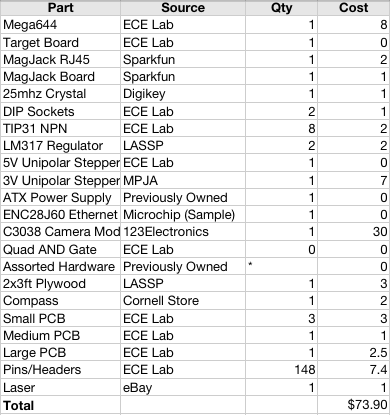
Part List:
For more detail: 3D scanner Using Atmega644