I know! You’re thinking: “Oh god… another ESP temperature and humidity silly project…” but wait! Here are the characteristics that might interest you:
- this data logger can run for 55 days before the memory is full (considering a 15 minutes sampling rate and a 64K SPIFFS)
- It can run for 43+ months before running out of battery (considering a 15 minutes sampling rate)
- You can easily turn on/off Access Point Wifi mode to pair it with your cell phone (or tablet, laptop etc.) to download the data in a snap! (<- that’s what is uncommon!)
Why I created that project? Because I needed to log the temperature and humidity with a 15 minutes rate during a 6 days backpacking expedition through the Gran Desierto de Altar (111+miles). I needed it to be cheap, reliable, precise, easy to use and most of all that could run for days without having to either free memory space or recharge the batteries.
How I built it? Follow the steps!
You love it? Please vote!
Here: https://www.instructables.com/contest/Microcontrol…
And here: https://www.instructables.com/contest/sensors2017/
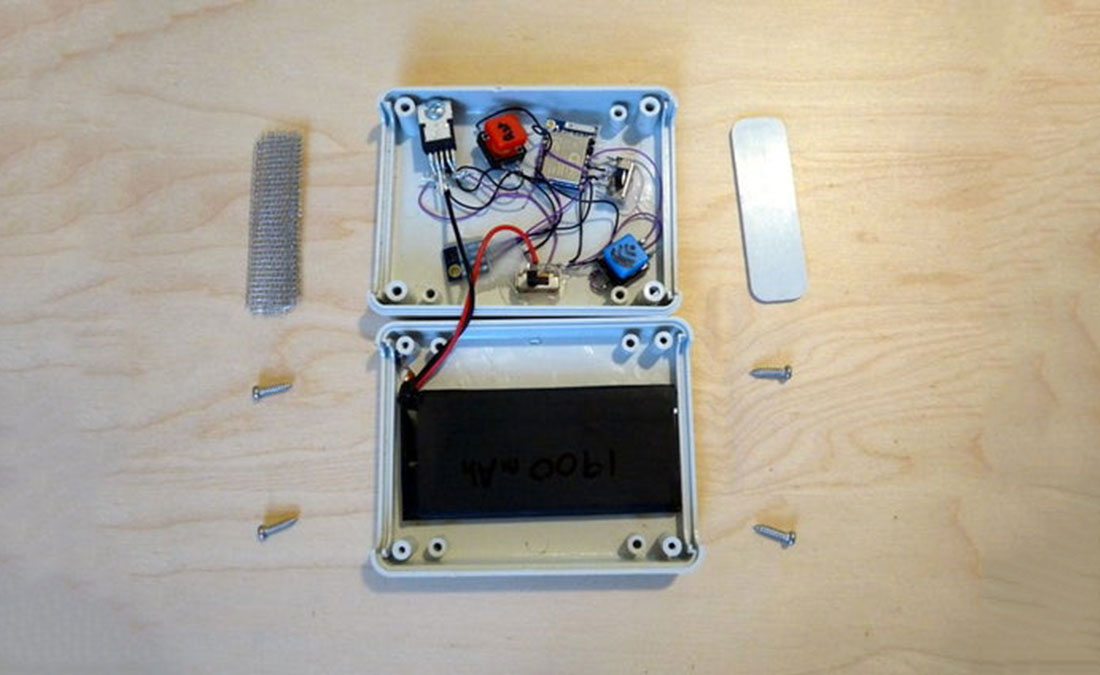
Step 1: Parts List
The pars are quite easy to find (Amazon, Ebay, local dealer etc.) and relatively cheap:
- 1 x ESP8266 version ESP07 (my favourite)
- 1 x SI7021 temperature and humidity industrial sensor, I2C connectivity
- 1 x LT1529-3.3 3.3V voltage regulator with ultra-low quiescent current
- 1 x 22µF 100V electrolytic capacitor
- 1 x 1900mAh 3.7V LiPo/Li-ion battery
- 1 x TP4056 Li-ion charger board
- 2 x single row male headers
- 2 x Slide switches
- 2 x Momentary push buttons
- 1 x Plastic enclosure
- 1 x piece of aluminium screen
You will also need regular electronics tools like soldering iron, pliers, wires etc., a hot glue gun and a FTDI232 3.3V programmer.
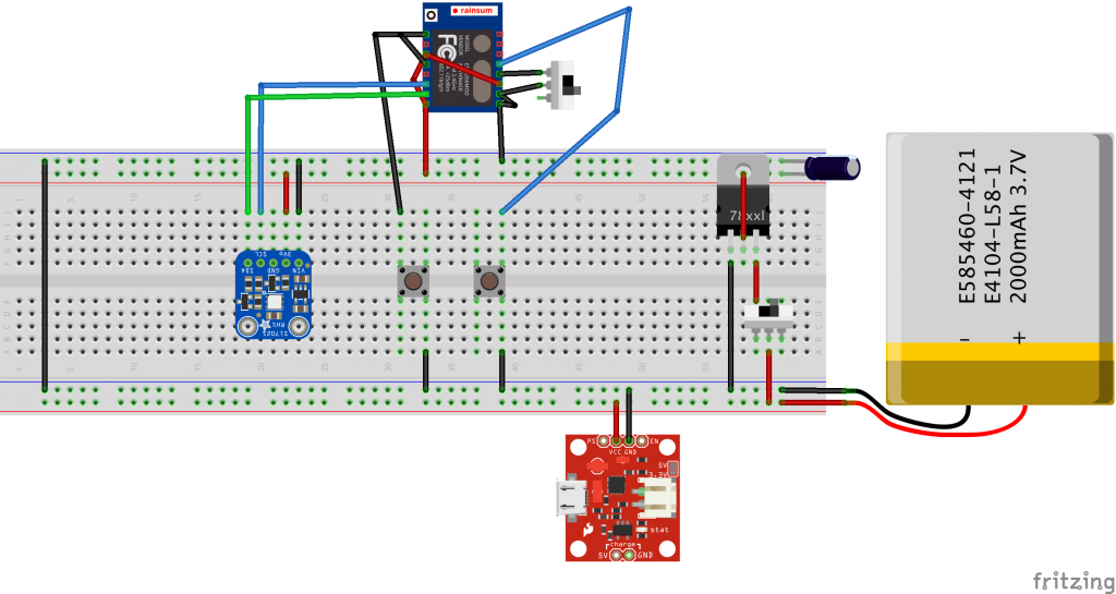
Step 2: Solder the Parts Together
We are going to build the circuit.
First we need to wire the ESP properly:
- wire GPIO15 to GND (mode configuration)
- wire GPIO02 to VCC (mode configuration)
- wire EN/CH_PD to VCC (to enable the chip)
- wire GPIO16 to RST (for the deep-sleep wakeup)
- wire a slide switch between GPIO00 and GND, we’ll name it program switch (to switch between running and programming mode)
- wire a momentary push button between GPIO04 and GND, we’ll name it Wifi button (to de/activate Access Point Wifi mode)
- wire a momentary push button between RST and GND, we’ll name it Reset button (to be able to reset the ESP at any time)
- solder the 2 headers to RX and TX (this will ease the connection between the programmer and the ESP)
Then we can connect the Temp. RH sensor to the ESP:
- wire SI’s SDA to ESP’s GPIO13
- wire SI’s SCL to ESP’s GPIO12
- wire SI’s GND to ESP’s GND
- wire SI’s 3.3V VCC to ESP’s VCC
Finally we need to build the power setup:
- wire battery’s Pos. to a slide switch
- wire the slide switch to LT’s VIN, we’ll name it power switch
- wire battery’s Neg. to LT’s GND
- wire LT’s SENSE to LT’s OUTPUT
- wire the capacitor between LT’s OUPUT and GND
- wire TP’s BAT Pos. to battery’s Pos.
- wire TP’s BAT Neg. to battery’s Neg.
Now we can pair the power circuit with the rest:
- wire LT’s OUTPUT to ESP’s VCC
- wire LT’s GND to ESP’s GND
At this point, you should be able to see the EPS’s and SI’s power LEDs turn on when switching on the power slide switch. If not, double check your circuit for openings and shorts, make sure your battery is fully charged.
The LEDs draw unnecessary current and must be removed by either desoldering them or carefully “destroying” them with pliers.
Here is a breadboard schematic view of the circuit, you can download the Fritzing file here.
Step 3: Send the Program to the ESP
To flash the ESP we will use the Arduino IDE. It’s almost as easy as flashing an Arduino.
Make sure the power switch is turner off.
First connect your FTDI programmer as follow:
| FTDI pin | ESP pin |
|---|---|
| RX | TX |
| TX | RX |
| GND | GND |
Do not connect FTDI’s VCC to ESP’s VCC as ESP is already powered by the battery and it could damage it.
Connect the programmer to your computer’s USB port.
Install Arduino IDE: see the first step of one of my Ibles.: https://www.instructables.com/id/IoT-Door-Alarm-UPGRADED/#step1
Download the SI7021 library and uncompress it in the Arduino’s Library folder: https://github.com/LowPowerLab/SI7021/archive/master.zip
Download the latest version of the code from my Github: https://github.com/ClemRz/EspDataLogger/archive/master.zip
Unzip the file in the Arduino’s folder and open EspDataLogger/software design/ESP8266_data_logger/ESP8266_data_logger.ino with Arduino IDE.
Set the program switch so there is continuity between GPIO00 and GND, this is program mode (V.S. run mode).
Turn on the power switch.
Push the Upload button of the Arduino IDE, the ESP should be flashed with the firmware smoothly.
Set the program switch to run mode.
Step 4: [Optional] Code Documentation
In this step I explain roughly how the software/firmware works.
There are 2 main “functions”:
- one that logs the temperature and humidity in a very power-efficient manner
- another that activate the wifi and provide a UI to serve data and parameters
When the ESP starts or wakeup, it runs the setup function where we read GIPO04, the one connected to the Wifi button.
- If this pin is high it means that the button is not pressed (due to internal pull up resistor). In this case we will read the sensor, store the value read into the file and go to sleep for an amount of time defined by the sampling rate parameter.
- If it is low, it means that the button is being pressed and instead of logging a new set of values we will activate the Wifi in the Access Point mode and serve a web page. This web page provide a form with different fields to allow visualisation, download and actions such as:
- delete the file from te EEPROM memory
- change the value of the sampling rate parameter (wakeup rate)
- reset the ESP
- etc.
If you want to know more about it feel free to check the readme file here.
Step 5: Preliminary Tests
Before moving everything into a nice enclosure we will make sure that it is working as designed.
Turn on the Access Point / Wifi doing the following:
- Make sure the circuit is energised
- Push and maintain pushed the Wifi button
- Push and release the Reset button
- Wait for 3 seconds
- Release the Wifi button
Using any wifi enabled device, like a smart phone, a tablet or a computer, search the open wifi signal named espDataLogger and pair with it.
Using a web browser on the paired device, visit the following url: http://192.168.4.1
You should see a UI similar to this one:
Source: Temp. and RH Data Logger With Wifi UI