Introduction
We designed and built a glove to be worn on the right hand that uses a Machine Learning (ML) algorithm to translate sign language into spoken English. Every person’s hand is a unique size and shape, and we aimed to create a device that could provide reliable translations regardless of those differences. Our device uses five Spectra Symbol Flex-Sensors that we use to quantify how much each finger is bent, and the MPU-6050 (a three-axis accelerometer and gyroscope) is able to detect the orientation and rotational movement of the hand. These sensors are read, averaged, and arranged into packets using an ATmega1284p microcontroller. These packets are then sent serially to a user’s PC to be run in conjunction with a Python script. The user creates data sets of information from the glove for each gesture that should eventually be translated, and the algorithm trains over these datasets to predict later at runtime what a user is signing.
High Level Design
Rationale
Our goal was to create a way for the speech-impaired to be able to communicate with the general public more easily. With a variety of sensors, we can quantify the state of the right hand in a series of numerical data. By collecting a moderate amount of this data for each letter or word and feeding it into a Machine Learning algorithm, it can train over this dataset and learn to associate a given hand gesture with its corresponding sign. We use Flex Sensors as variable resistors to detect how much each finger is bent, and the MPU-6050 can identify the orientation and hand movements that the Flex sensors cannot capture. Moreover, to discern between extremely similar signs, we add contact sensors to the glove to gather additional information.
Logical Structure
Each Flex Sensor is treated as a variable resistor whose resistance increases as the sensor is bent. Each sensor constitutes a part of its own voltage divider circuit, whose output is processed through one of the microcontroller’s (MCU) analog-to-digital converters. The analog voltage input into the MCU changes as a function of how much the corresponding finger is bent, and the MCU’s resulting digital information can be read by the translation script to describe a certain sign.
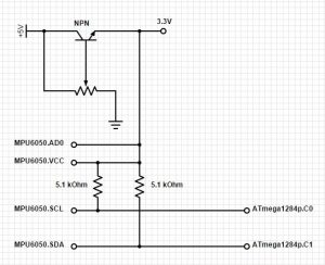
The MPU-6050 uses an I2C interface to communicate with the MCU, and uses the dedicated SDA bus to send the accelerometer and gyroscope data to the MCU when desired.
Moreoever, contact sensors in the form of copper tape are used to create a binary input value to the MCU to represent any contact or lack thereof.
At regular intervals (as often as possible), the MCU gather the data it has read into a packet, and send the packet via serial bus to a PC.
The python algorithm is composed of a serial wrapper to handle communications with the glove, a script that gathers data and stores it in a data structure, a script that performs the learning and prediction, and a few scripts that help to visualize sensor and classification data as well as some troubleshooting. Overall, the python software is in charge of gathering the data from the MCU and learning the required classification.
Hardware/Software Tradeoffs
MCU vs CPU: One of the big issues with Machine Learning is that, depending on the function being learned, the nature of the data, and the size of the dataset, the process can be quite resource intensive. For this project, we decided to move much of the computation onto the PC for several reasons. First of all, it makes sense to perform the training on a powerful system since this is by far the most computationally expensive part of ML. This is a common practice in the field and it also provided us with the flexibility of using many of the already implemented ML algorithms available. Having the data on a PC also gives the developer the chance to visualize the data and maneuver it in much more powerful ways while ignoring many of the headaches that come from debuging algorithms of this complexity on a MCU with limited visibility. Due to the limited development time, the fact that so much of the infrastructure was already implemented on the PC, and the additional computation power, we also chose to do classifications on the computer as well. As previously mentioned, depending on the learning algorithm that is used, the prediction can be quite efficient or expensive. We plan to try various approaches in the future and thus it makes more sense to continue our experimentation on the PC before committing to implementing the ML algorithms from scratch on the MCU. It is also a well known fact that as time goes by, the computational power that we can pack in small processors increases drastically. Since the project being presented is just a prototype of a possible product, it is not clear that constricting the processing power of the design would benefit – as a matter of fact it may even be detrimental to – the final design.
Prediction without Button Push: One of the design decisions that we came across was how to let the microprocessor know that a sign was being made. One of the options was to have a single push button that would be pressed when we wanted the system to start predicting. Instead, we allowed the software to make this decision. We did this by adding a “nothing” and “relaxed” to the possible predictions which became the outputs of the system when nothing is being signed or when the hand is at the user’s default pose.
Designation of Sensor Pins: One of the benefits of using ML approaches to do gesture recognition was the fact that we, as designers, did not have to worry as much about individual sensor/pinout configuration. Since the algorithms are indifferent to which value is coming from the index vs which value is coming from the x-axis accelerometer, we had a lot of flexibility when it came to physical configuration of the system. Furthermore, we were able to compensate for the variation in sensor ranges and data types through individualized normalization on the software side. This mean that we didn’t have to force sensors like the flexors into outputting a 0 to 5 volt signal.
Changes from Initial Prototyping: Another tradeoff that we made under the given time constraints was to focus more on accuracy than on portability. We would like to take the design to a stage where the glove is a stand alone device that can communicate wirelessly with other devices such as a cellphone or the PC. We decided leave this and other ideas to be implemented at a later time since they would require fiddling with additional hardware that was not necessary for the initial proof of concept.
Standards and Patents
There seems to be other devices and patents that aim to do the same process of translation of sign language into speech. In most of these cases it seems that the inventors augment the device with several more sensors than what we use, but we hold no claim of originality.
Sign language editing apparatus; Inventor: Ikeda, et al.; PN 5,990,878
A sign language editing apparatus includes a glove-type sensor for converting movement of fingers in the sign language into an electrical signal to produce time series data of sign language words, a sign language word data editing device for adding predetermined additional data to the time series data inputted from the glove-type sensor to process the time series data, a sign language word dictionary for storing the time series data of sign language words processed by the sign language word data editing device, a sign language sentence data editing device for reading out the time series data of sign language words stored in the sign language word dictionary in accordance with the predetermined characters inputted from the input unit and adding predetermined additional information to the time series data of sign language words to produce time series data of sign language sentence, a sign language animation synthesizing device inputted with the time series data of sign language sentence produced by the sign language sentence data editing device to produce sign language animation expressing movement of the sign language, and a display unit for displaying the sign language animation produced by the sign language animation synthesizing device.
Method and apparatus for translating hand gesturs; Inventor: Hernandez-Rebollar; PN: 7,565,295
A sign language recognition apparatus and method is provided for translating hand gestures into speech or written text. The apparatus includes a number of sensors on the hand, arm and shoulder to measure dynamic and static gestures. The sensors are connected to a microprocessor to search a library of gestures and generate output signals that can then be used to produce a synthesized voice or written text. The apparatus includes sensors such as accelerometers on the fingers and thumb and two accelerometers on the back of the hand to detect motion and orientation of the hand. Sensors are also provided on the back of the hand or wrist to detect forearm rotation, an angle sensor to detect flexing of the elbow, two sensors on the upper arm to detect arm elevation and rotation, and a sensor on the upper arm to detect arm twist. The sensors transmit the data to the microprocessor to determine the shape, position and orientation of the hand relative to the body of the user.
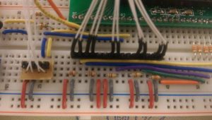
Hardware
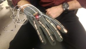
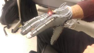
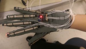
The physical product is comprised of a glove onto which the various sensors and necessary wires were sewn. Each finger has one Flex Sensor stitched on the back-side of the glove, and MPU-6050 is attached to the center of the back of the glove. For two contact sensors, copper tape was afixed to four key locations.
Voltage Divider Circuits
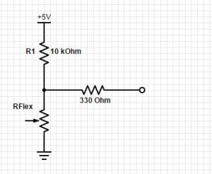
Since each Flex Sensor has a resistance that varies depending on how much the finger is bent, we attach each Flex Sensor as part of a voltage divider circuit (shown as R2 above) in order to obtain a corresponding voltage that can then be input into the MCU.
Vout = Vin * ( R1 / (R1 + R2) )
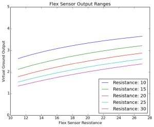
We determined a good value for R1 by analyzing expected values from the Flex Sensor. Each one has a flat resistance of 10kOhms and a maximum expected resistance (obtained by measuring its resistance on a clenched fist) of about 27kOhm. In order to obtain the maximum range of possible output voltages from the divider circuit given an input voltage of 5V, we plotted the expected ranges using the above equation and values of R1 in the range of 10kOhm to 22kOhm. We found that the differences between the ranges were negligible, and opted to use 10kOhm for R1.
Our resulting voltage divider has an output range of about 1V. We were initially concerned that the resulting values from the MCU’s analog-to-digital converter would be too close together for the learning algorithm to discern between different values sufficiently. We planned to address this by increasing the input voltage to the voltage divider if necessary, but found that the range of voltages described earlier was sufficient and performed extremely well.
Voltage Regulator
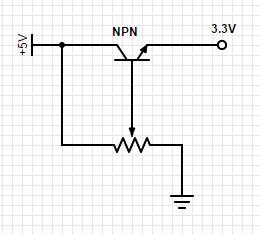
The MPU-6050 operates on a lower VCC (3.3V) compared to the MCU’s 5V. So as not to burn out the chip, we created a voltage regulator using an NPN transistor and a trimpot, connected as shown. The trimpot was adjusted so that the output of the regulator reads 3.3V. This voltage also serves as the source for the pull-up resistors on the SDA and SCL wires to the MCU. Since the I2C devices are capable only of driving the input voltages low, we connect them to VCC via two 4.7kOhm pull-up resistors.
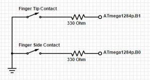
Contact Sensors
As described later, we found that we needed to add contact sensors to several key spots on the glove. These would essentially function as switches that would pull the MCU input pins to ground to signal contact.
Sensor Mounting
Aside from the hardware and software functionality of the device, we had to ensure that it was both comfortable and sturdy. The flex sensors were stitched onto the glove so that they could slide naturally as the user flexes his or her fingers without slipping around (which would result in inconsistent data during training and translating). Similarly, the MPU-6050 chip had to be located such that the glove’s fabric would not bunch up underneath it and skew the orientation. Lastly, wires had to be stitched to the glove so that they would not get caught on anything while signing.
Software
I2C Communication
Interfacing with the MPU-6050 required I2C communication. The ATmega1284p does not have any dedicated I2C libraries, so we opted to use Peter Fleury’s public I2C library for AVR microcontrollers. I2C is designed to support multiple devices using a single dedicated data (SDA) bus and a single clock (SCL) bus. Even though we were only using the interface for the MCU to regularly poll the MPU-6050, we had to adhere to the I2C protocol.
Fleury’s library provided us with macros for issuing start and stop conditions from the MCU (which represent different signals that the MCU is requesting data from the MPU-6050 or is releasing control of the bus). These provided macros allowed for us to easily initialize the I2C interface, set up the MPU-6050, and request and receive the accelerometer and gyroscope data (described later).
Reference: Peter Fleury’s I2C library for ATmega1284p (see Appendix E)
Watchdog Timer
While testing our I2C communication with the MPU-6050, we found that the MCU would occasionally hang while waiting for data from the I2C bus. To prevent this from stalling our program, we enabled a watchdog timer that would reset the system every 0.5 seconds, unless our program continued to progress to regular checkpoint intervals, at which time we would reset the watchdog timer to prevent it from unnecessarily resetting the system. We were able to leverage the fact that our MCU’s work consists primarily of continuously collecting sensor data and sending packets to a separate PC. This allowed us to simply have the timer reset the system and avoid unnecessary interrupt service routines.
TinyRealTime
For the majority of the code we used Dan Henriksson’s and Anton Cervin’s TinyRealTime kernel. The primary reason for using this kernel is that we wanted to take advantage of the already implemented UART library in order to communicate with the PC. The main task first initializes the IMU, the I2C, and the ADC. After it enters an infinite loop it resets the watchdog timer and gets 16 readings from all of the sensors – accelerometers, gyroscopes, flex sensors, and touch sensors. We then take all of the sensor values and compute filtered values by summing all of the 16 readings from each sensor. Since summation of the IMU sensors can produce overflow, we make sure to shift all of their values by 8 before summing them up. The data is then wrapped up into byte array packet that is organized in the form of a header (0xA1B2C3D4), the data, and a checksum of the data. Each of the sensors is stored into two bytes and the checksum is calculated by summing up the unsigned representation of each of the bytes in the data portion of the packet into a two byte integer. Once the packet has been created it is sent through the USB cable into the computer and the process repeats.
Machine Learning Algorithm and Putting it All Together
There are two main modes of operation for this project. The first is for gathering data. In this mode you can tell the computer what the label that you will be recording is (for example ‘a’, ‘b’, etc.) or you could chose to record from a full alphabet (with “nothing” and “relaxed” included). During these processes the software will create an instance of a SerialWrapper object which will gather data from the glove at the fastest possible rate. Once all of the desired data has been gathered, the program can be stopped and the data can be discarded or stored. The second mode provides continuous predictions through visual and verbal feedback. The software will create a SerialWrapper object and continuously poll it for new packets. Once a packet is received, the data is processed and a prediction is made. This prediction is then fed into a buffer and a one more filter is applied to the data in the buffer before the final prediction and output is produced.
The SerialWrapper object’s main goal is to receive data from the MCU. It does so by opening a port and running a separate thread that waits on new data to be available. The data is then scanned for the header and a packet of the right lenght is removed when available. The checksum is then calculated and verified and if valid, the data is unpacked into the appropriate values and fed into a queue for other processes to extract.
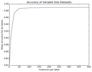
For this project we made use of Support Vector Machines (SVM) or Support Vector Classifiers (SVC) as our ML approach for classification of signs. This approach works well for various kinds of data, but was initially unable to handle prediction with our data in its unprocessed format. The issue arose from the fact that we used various sensors and that their ranges and distribution of values varied greatly. The solution was to take the full data set and calculate the average and variance of each of the sensors and then use that to normalize the data so that each of the sensors would end up with a mean of zero and with unit variance. The transformation was then applied to all of the sensor inputs before training and prediction. The result was that the classifier went from random guessing to a 98% accuracy on the full dictionary of labels.
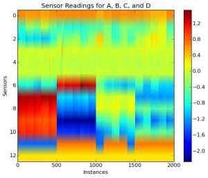
Another part that was crucial to us as developers was the use of plotting in order to visualize the data and qualify how well a learning algorithm should be able to predict the various signs. The main tool that was developed for this was the plotting of a sequence of sensor readings as an image. Since each packet contained a value for each of the sensors (13 in total), we could concatenate multiple packets to create a matrix. This matrix could then be plotted with instances of the same sign grouped together and the differences between these and the others could then be observed. If the difference was clear to us, then the learning algorithm should have no issue telling them apart. If this was not the case, then it is possible that the algorithm could struggle more and changes to the approach could have been necessary. As you could see below, there are 4 clear divisions as we move our eyes from left to right. These correspond to the letters or signs being sensed.
As previously mentioned, the output of the classifier goes through a final level of filtering and debouncing before the output reaches the user. To accomplish this, wie fill up a buffer with the last 10 predictions and only consider something a valid prediction if it has been predicted for at least 9 out of the last 10 predictions. Further more we debounce this output and only notify the user if this is a novel prediction and not just a continuation of the previous.
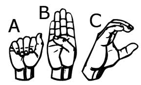
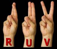
Modifications from Initial Prototype
Our original glove did not have contact sensors on the index and middle fingers. As a result, it had a hard time predicting “R,” “U,” and “V” properly. As you can see from the correct signs below, these signs are actually quite similar to each other in terms of hand orientation and flex. To mitigate this, we added two contact sensors: one set on the tips of the index and middle fingers to detect “R,” and another pair in between the index and middle fingers to discern between “U” and “V.”
We considered implementing a glove that could communicate with the PC wirelessly using Bluetooth, but opted to do so only if we had enough time (which we didn’t).
Results
Speed of execution
We determined how quickly we could send data to the PC by sending data serially and increasing the send rate until we noticed a difference between the rate at which data was being received and the rate at which data was bing sent. We then reduced the send frequency back to a reasonable value and converted this into a loop interval (3 milliseconds).
We aimed to gather as much data as possible from the sensors in between packet transmission. To accomplish this we had the MCU gather as much data as possible in between packets and in addition to sending a packet, it also sent the number of readings that it had performed. We then used this number to come up with a reasonable number of values to poll before aggregating the data and sending it to the PC. We concluded that the MCU was capable of reading and averaging each of the sensors 16 times each.
The python algorithm is currently limited by the rate at which the MCU sends data to the PC and the time that it takes the speech engine to say the word or letter. The rate of transfer is currently about 30 Hz and we wait to fill a buffer with about 10 unanimous predictions. This means that the fastest that we could output a prediction would be about 3 times per second which for our needss was very suitable.
Accuracy
The averaging we do at each interval helps to account for any noise or glitches that the flex sensors are sometimes prone to.
The accuracy of the glove is also somewhat limited by the size of the person’s hands. The accuracy of each flex sensor is limited beyond a certain point. Smaller hands will result in a larger degree of bend. As a result, the difference between slightly different signs with a lot of flex might be too small for users with small hands. For example, consider the signs for “M” and “S.” The only difference between these signs is that “S” will elicit slightly more flex in the fingers. However, for smaller hands, the change in the resistance from the flex sensor will be negligible, and the algorithm may be unable to discern the difference between these signs.
Since we know that serial communications is prone to data corruption and the learning on incorrect data has undesired consequences, we chose to implement a checksum for the packets being sent. This approach not only made the packet reception simpler, but it also provided fairly strong guarantees that the data being received was indeed what was sent by the MCU.
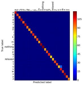
As previously mentioned, out current classifier is able to achieve an accuracy of 98% on a task of 28 signs, the full alphabet as well as “relaxed” and “nothing”. On the other hand, a random classifier would guess correctly 4%, clearly indicating that our device is quite accurate. It is however worth noting that the algorithm could greatly benefit from improved touch sensors (seeing as the most comon mistake is confusing u for v), being trained on a larger population of users, and especially on larger datasets. With a broad enough data set we could provide the new users with a small test script that only covers difficult letters to predict and relies on the rest of learned data for the rest. The software has currently been trained on the two team members and it has been tested on some users outside of the team. The results were excelent for the team members that trained the glove and mostly satisfying though not perfect for the other volunteers. Since the volunteers did not have a chance to train the glove and were not very familiar with the signs, it is hard to say if their accuracy was a result of overfiting, unique signing, or inexperience with ASL. Regardless, the accuracy of the software on users who trained was near perfect and mostly accurate for users that did not know ASL prior to and did not train the glove.
Safety and Interference with Other Devices
Our device uses a low voltage environment, and extremely low frequency communication. The sensors are well-attached, and there are no sharp edges. As a result, we don’t see any large safety issues associated with the glove.
Furthermore, since all communication is done via cables, our device does not interfere with other designs.
Usability
The glove can be used by anyone who fits into it, they would only have to train on it and generate new datasets if they wish for a higher prediction accuracy than the standard or to incorporate new signs. It is targeted for use by people with special needs who cannot speak, but can certainly be generalized to gesture recognition, not just signing. The labels for each dataset need not be converted to speech, and can be used as a “command” for other interfaces, such as interactive computing spaces or games.
Conclusion
Our Expectations
The project was able to meet our expectations quite well. Our initial goal was to create a system capable of recognizing and classifying gestures and we were able to do so with more than 98% average accuracy across all 28 classes. While we did not have a solid time requirement for the rate of prediction, the resulting speed made using the glove comfortable and it did not feel sluggish. Having had more time available, or going forwards with the project, it would make sense to improve our approach for the touch sensors since the majority of the ambiguity in signs come from the difference between ‘u’ and ‘v’. We would like to use materials that lend themselves more seamlessly to clothing and provide a more reliable connection. In addition we hope to make the glove wireless, therefore allowing it to easily communicate with phones and other devices and making the system truly portable.
Applicable Standards
American Sign Language standards: For gestures we adhered to the signs established by communities such as the American School for the Deaf and the National Association of the Deaf.
I2C and USB standards: Though we did not have to worry about this ourselves, the libraries that we used for I2C and serial communication with the PC adhered to the propper standards as well.
Intellectual Property Considerations
The MCU’s software was based on the TinyRealTime (TRT) kernel written by Dan Henriksson and Anton Cervin in 2004. The source files were used with permission given by Cornell University.
When we came up with the idea for our project, we were not aware of any other similar designs. We later discovered that there was a similar project from last year, but our design is different in that we purchased flex sensors rather than built our own, and used cables rather than implement a wireless glove. Moreover, our project uses a Machine Learning algorithm that can train over any input selected by the user, and can thus be generalized to gesture recognition, rather than just sign language translation. Other projects more similar to ours in hardware have been published online, but we were also unaware of these projects, and did not look into them and did not intentionally use any aspects of someone else’s design.
Code from the Public Domain:
We used the I2C library, written by Peter Fleury, for use with I2C communication between the MPU-6050 and the ATmega1284p. This code was made available via the public internet (see Appendix E).
Most of the Machine Learning algorithms came from scikit-learn, a large ML library available to Python.
We also used the public Python text-to-speech library pyttsx for the text-to-speech conversion in order to output audio for each sign.
Patent/Trademark Issues, Non-Discosures: We are not reverse-engineering a design. As such we do not have to address any patent or trademark issues. Furthermore, we did not use any sample parts. Since we purchased everything, we did not have to sign any non-disclosure agreements.
Patent/Publishing Opportunities: We do not expect to be able to investigate any patent opportunities for our project. There are, however, numerous publishing opportunities in conferences or journals that we may choose to investigate.
Ethical and Legal Considerations
We believe that every human being has the right to express themselves and communicate their thoughts. For some time there has been a push in our community to reword the expression “a disabled person” into the phrase “a person with disabilities”, because we believe in the importance of stating that they are a person before claiming that they posses a disability. And just like many will agree “It’s not a ‘disability’. It’s a different ability.” While some people may not communicate in the same verbal way that many of us do, they posses the ability to use their hands in order to express their thoughts. The only issue is that technology has not yet pushed enough to allow the rest of us to understand this language. While there may be many applications to gesture recognition systems, we chose to specifically tailor this project towards the deaf community. The technologies and approaches that we are presenting have been around for some time, but we have seen a lack of application in a field such as this, which could drastically improve the life of many. We do not present an ultimate solution, but we hope to show that it is possible to build simple and efficient systems to help bridge the gap between communities that share their thoughts through different means.
With regards to the development of our device: All of the people who trained or tested with our system were volunteers or the developers themselves. No potential harm was ever present and full explanation of the project and its goals was given to them. If further development was pursued in the hopes of marketable technology, we would then be obliged to address several other issues (for example: compensation). However, that is not the purpose of this design.
Moreover, all those who contributed to the development of this project to help make it a success are acknowledged in this document.
Furthermore, all claims that we make in this document regarding our device are honest and realistic. Any deficiencies in our device have been addressed to the best of our abilities, and have been acknowledged in this document. All credit that is due to persons outside of the group have been referenced and acknowledged where necessary.
Finally, our device does not require any technology that is subject to any known legal restrictions. All communication is done via wires, and components were purchased legally online.
Source: Sign Language Glove