Summary of AccelCar
The AccelCar project transforms a Wii Remote-like experience into real life by controlling an RC car via tilt angles. Using a gyroscope/accelerometer module, the remote sends Bluetooth data to the car, which adjusts motor speeds and directions based on pitch and roll calculations. The team selected DC motors over servos or brushless motors for speed and torque balance, chose plywood for the chassis due to ease of modification, and utilized HC-05 Bluetooth modules for communication. The system includes emergency stops on both the remote and car to ensure safety during operation.
Parts used in the AccelCar:
- Atmega1284P microcontroller
- MPU-6050 accelerometer/gyroscope sensor (GY-521 breakout board)
- HC-05 Bluetooth transceiver module
- DC motors with gearbox
- TB6612FNG H-Bridge motor driver breakout board
- 4 AA battery pack (6V power source)
- 9V battery (for microcontroller)
- Voltage level converter/shifter
- Plywood chassis
- Emergency stop push button
- Ball bearing wheel
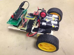
Our project aims to take the fun of a Wii Remote and translate it to real life. The AccelCar is a remote-controlled car that is controlled by the way that a user tilts the remote, similar to the way Mario Kart Wii is played. The angle of the tilting determines the speed and direction in which the car should move.
The remote control consists of a gyroscope/accelerometer module, which is used to find the angle at which a user is tilting the remote. That information is sent over Bluetooth to the RC car, where those values are used to spin two wheels at the right speed and direction to get the car where it needs to go.
Our motivation for this project was to create a neat toy with unique controls that can be played by people of all ages.
High Level Design
Rationale and Inspiration
Originally, our plan was to create a quadcopter which was controlled in a similar manner to AccelCar’s controls. We wanted to make something that could move around and interact with the physical world. Defying gravity was something we thought would be very cool to try, but unfortunately, some of the components we had did not work, and there were tight time constraints in terms of shipping in new components. Therefore, we changed the quadcopter into a remote-controlled car. For more information about the quadcopter, please see to the quadcopter section in the Appendix.
Background Math
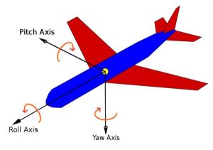
To calculate the angle at which the remote control was, we used the following equations:
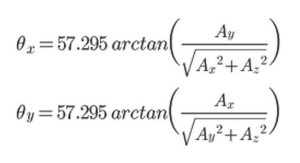
where θx and θy are the pitch and roll of the accelerometer, and A* is the measured acceleration data from the accelerometer module for the specified axis. (Source) Since the “atan” function in C’s “math.h” library returns the inverse tangent in radians, 57.295 factor simply converts the value from radians to degrees.
Mapping Angles to Speed and Direction
Once the tilt angle of the remote could be easily accessed by the microcontroller, we needed to figure out how to change the speed and direction of the car based off of these tilt angles. We decided to map the tilt angles linearly to the speed of the motors. Since the speed is controlled by the duty cycle of the PWM signal going from the MCU to the motor driver, this simply meant mapping 0-90 to 0-255. In addition, the angles are signed (i.e., the X-angle is negative if the remote is tilted forward and positive if the remote is tilted backwards), so the signs of the angles determined whether the wheels rotating forward or backwards. Negative angles simply translated to spinning the wheel in the opposite direction; we never set OCR0A or OCR0B to negative values. Thus, if the remote was only tilted forward or backward (with no side-to-side tilting) then the PWM values for the left and right motors (OCR0A and OCR0B) would be:
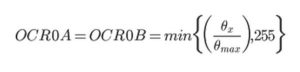
where θx is the pitch of the remote control, and θmax is the tilt angle at which we want the motors to go full speed (60-70 degrees, since that is the greatest angle that a user would feel comfortable tilting the remote). Also, since it is possible for θx to to be greater than θmax, we check the bounds on the calculated value to ensure that neither OCR0A nor OCR0B overflow.
The tricky part was determining how to change the PWM duty cycle for each motor so that the two motors would mirror the side-to-side angle of the remote. We wanted the speed of the turn to be related to both the pitch and roll of the remote. In other words, the more the remote was tilted forward/backward, the faster the turn would be; similarly, the more the remote was tilted left/right, the tighter the turn would be.
We determined that, in order have a quick turn for a large pitch and slower turn for a smaller pitch, the PWM values would have to be modified from the OCR0A/B calculated from the equation above. Furthermore, the tighter the turn, the greater difference we would need between the speed of the two wheels. We decided that for a right turn, we would keep the right wheel speed proportional to the pitch while also decreasing the left wheel speed. In short, the greater the sideways angle of the remote, the greater the decrease for the left wheel, and vice versa for a left turn.
If the remote was tilted sideways at its maximum angle, we want the tightest turn that we could get, so the wheels would be travelling in opposite directions (1 forward, 1 backward). Thus, if the car was tightly turning right, then the amount to subtract from the left wheel speed would be twice of what it originally was. If we wanted the car to turn less tightly, it would correspond to a smaller sideways tilt, and we would simply subtract less. So calculating the OCR0* for the slower motor is as follows:
where θy is the angle of the remote’s roll, and θmax is the tilt angle at which we wanted the car to have its tightest turn.
The figure below describes how the wheels turn relative to the rest of the car when the car is moving forward, moving backward, making a sharp left turn, and making a sharp right turn. The diagrams are a top view of the wheels, and the front of the car is the top of the figure.
Logical Structure
Our project is structured so that it breaks down into two main components: the remote and the car. The operation of our car is summarized in the diagram below:
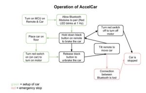
The three different modes of operation are just setting up the car, running the car, and stopping the car. Setting up the car is highlighted in green. Running the car normally is highlighted in black, and should the car lose Bluetooth connection with the remote, the car has a emergency stop.
Hardware Tradeoffs
Some considerations between possible hardware that could be used as opposed to the hardware that was chosen for the final project were:
- DC motors vs. brushless motors vs. servos
- Handwritten radio frequency protocol vs. Bluetooth communication
- Plywood vs. acrylic car body
To go into more detail about 1, we chose to use DC motors, because when they have a gearbox, the car can run at a smooth and reasonable speed with enough torque to move the entire body of the car. Servos could replace the DC motors, but they generally run slower in terms of RPM with more torque. Due to our goal of making our car more of a real life Mario Kart, we eliminated the servo since it could run the car at a faster speed, even though it did move the car pretty well. Using the servos could give us more flexibility in designing the physical body of the car, as the car could be much heavier and the servos could move the car without any problem. There was no reason to have a bulkier car (unless we wanted our car to carry a lot of weight or push heavier objects such as other robots); thus, we eliminated the servo. The brushless motors that we managed to scrap from the old quadcopter project (add link to project?) had high rpm, but they required the use of motor controllers and a programming card to operate them. Due to timing constraints and that the brushless motors were designed for the use of quadcopters, we went with the DC motors.
The second hardware tradeoff was choosing between using Bluetooth and writing our own RF communication protocol between the remote and car. The benefits of regular RF communication are that it has longer range and is faster than Bluetooth. The disadvantages of using RF are that we would have to make sure we were not violating any rules regulating the radio frequency band, and whatever protocol we chose to use would have to be written by us. The benefits of using Bluetooth communication are that Bluetooth is widely used, and we did not have to worry as much about violating FCC rules that regulate the frequency band, as Bluetooth is used for data exchange over short distances. The only disadvantages of Bluetooth are that it is slower, and it appeared that our Bluetooth modules would only be able to communicate over short distances. Since the RC car does not operate at high speeds, the slower communication is not a huge issue. Also, we do not want to communicate with the car at a distance where we cannot visibly see the car, so the short range communication distance of the Bluetooth is not too much of a problem, either. Furthermore, through testing of our AccelCar, we determined that our Bluetooth modules actually have quite a large range. Another benefit is that since Bluetooth is so standardized, any smartphone could easily communicate with the car if we configured the modules to pair with any Bluetooth device, and a smartphone with an accelerometer could easily act as a remote in place of the remote we have created. A final advantage to using Bluetooth was that a previous ECE 4760 group, Ellen Chuang and Julie Wang (Wireless Pedometer), already had useful documentation for using the HC-05 Bluetooth module, so this implied easy setup.
The final tradeoff between hardware was choosing between the material for the body of the car. We had a choice between acrylic and plywood, and we chose plywood over acrylic, because plywood is very easy to drill holes into to customize the motors to mount onto the body easily. Acrylic requires a special drill bit to create a hole, which Phillips 238 does not seem to have. It is very likely a drill bit could be cracked if used incorrectly. In addition, the acrylic would have to be laser cut to get the rectangle shape of the body. The plywood was easier to cut with a saw, so we used the plywood in favor of the acrylic.
Software Tradeoffs
Some tradeoffs between software were designing our own communication protocol versus using the Bluetooth protocol. While designing our own RF protocol would have meant that communication between the remote and car would be faster, we decided to use prepackaged Bluetooth instead, because speed was not as much of an issue for this project, and because we felt that the time spent sorting out bare RF would be better spent elsewhere.
Another software tradeoff was deciding whether or not to take advantage of the accelerometers and Bluetooth capabilities of cell phones, in order to make our device even more extensible and user friendly. We decided not to do this due to time constraints, but it would certainly be possible to do this.
To avoid jitter in the angles sent from the remote, we only send values from the remote every 100 ms. This is still fast enough to achieve relatively seamless controlling.
Standards
Our final project utilizes a HC-05 Bluetooth transceiver module which complies with the Bluetooth 2.0 standards. In addition, Peter Fleury’s I2C C library was used to communication with the MPU-6050 accelerometer/gyroscope sensor.
Existing Products
We found several projects online that are similar to ours, in that they are remote-controlled cars whose motions are controlled by the tilt angle of the controller. They differ from our project in the type of remote control that is used and in the way that data is transmitted from the remote to the car.
A previous ECE 4760 project, Accelerometer Controlled R/C Vehicle (Fall 2008), is based on a similar concept and was created for similar reasons (ease of use and fun), but it uses regular RF instead of Bluetooth to send data to the car.
The Accelerometer Car project on Instructables [link] also uses a regular RF receiver/transmitter to communicate between the car and remote.
The Arduino Android Gyroscope Bluetooth-Controlled Car on YouTube [link] uses the accelerometer/gyroscope and Bluetooth on an Android phone in much the same way that we did for our remote.
Lasty, the ROBOCar [link] uses a Raspberry Pi on the car and an actual Wii Remote as the controller.
While various incarnations of this project have been done in the past, our project still presented unique challenges in the way that our various components and modules worked and interacted.
A quick search of Google Patents [link] reveals that U.S. Patent US8106748 details a similar structure to the one in our project, but our project differs from the patent in that our remote control only has accelerometer sensing, with no manual input mode.
Overall Design Approach
The design of the AccelCar involves the construction of two components: the remote and car.
As can be seen in the diagram above, the remote is composed of the Atmega1284P microcontroller, an accelerometer/gyroscope sensor where the microcontroller obtains data from the chip, and a Bluetooth transceiver to transmit commands to the car. On the car side, the microcontroller controls the direction and speed of the motors as well as receives the commands from the remote through its Bluetooth transceiver.
Software Design
As mentioned earlier, our entire project was broken down into two main components: the remote and car. Since these are two physically different components, the software for them are different from each other.
Remote
The remote is composed of two main hardware components: the accelerometer/gyroscope breakout board and the HC-05 Bluetooth transceiver. The software of the remote therefore involved integrating the information received from and sent to these two components.
Gyroscope/Accelerometer
The accelerometer board utilizes I2C protocol to communicate the values of the acceleration vector of the board on the xyz plane. Therefore, we had to set up an I2C library in our code for the remote to do basic I2C signals such as the start and stop signals. We utilized Peter Fleury’s I2C library for AVR which contained these basic functions. We also referenced Brian Harding’s I2C code from the Spring 2011 project, FaceAccess [link], as an example of using Peter Fleury’s library.
To get the accelerometer to return data to the microcontroller, it was very important for us to read from the MPU-6050 datasheet and register map which had all of the relevant information for the sequence of commands we should send out to the accelerometer in order to get information or write information to the board. Here is some of the information that was pulled from the data sheet that is useful for understanding how I2C worked with the accelerometer board.
The HC-05 Bluetooth module is meant to be plug-and-play using the MCU’s UART pins. While we had some issues setting up the modules, once the hardware was set up, sending information over the Bluetooth modules was as simple as sending information to stdout and reading information from stdin. From the remote, we sent ordered pairs of integers, made up of the tilt on the x angle and the tilt on the y angle of the accelerometer. The Bluetooth module on the car receives those pairs and scans in the angles so that they can be converted to appropriate PWM values for the motors.
We actually had some trouble reading in stdout (e.g., getting garbage data, getting only some values, etc.). When we were sure that the issue was not in hardware (i.e., baud rate, pin connections), we fixed the software as follows: We ensured that the format we were scanning from stdin was the same as what was being sent (printed) to stdout. We used TinyRealTime so that motor control code was not interfering with reading in from the UART. fscanf for stdin is delimited by whitespace, so the ordered pairs being sent over Bluetooth cannot have spaces. In other words, we send (x_angle,y_angle) and not (x_angle,<space>y_angle).
Emergency Stop Button
The remote also has an “emergency stop” push button, which can be used to stop the car remotely. When this button is pressed, it pulls the interrupt pin of the MCU (pin D.3) HIGH; when it is released, this pin is LOW. Thus, our remote code enables the external interrupt and has one interrupt service routine (ISR). The ISR is triggered on either a positive or negative edge of D.3, so when the button is pressed and held down, the ISR sets a flag that says that the car should stop. When the button is released, the ISR clears that flag. This flag is checked each time before the Bluetooth module sends a message over UART, to see if the message sent should be the actual angles read in by the accelerometer or just zeros.
Car
The program on the car involves reading in data from the Bluetooth module (see section above for details), then mapping the angles read in (through UART) from the module to PWM signals. These two steps are done in two separate tasks on TinyRealTime so that angles can be read in parallel to the PWM values being updated. The mapping from angle to PWM value simply implements the math discussed in the “Background Math” section above.
The car also has an emergency stop, which is activated when a pin connected to the STATE pin of the HC-05 becomes LOW. This part is done by polling, since checking the state of one pin does not take much extra time and because, due to the slow speed of the car, we can afford to wait a couple extra milliseconds between polls.
Hardware Design
As mentioned earlier in the Overall Design Approach section, there were two main hardware components: the car and remote. The figure above shows how the hardware would interact with each other.
Remote
A more specific schematic of the remote is shown in the Schematics section of the Appendix.
On the remote, there is a HC-05 Bluetooth Module that is powered by 5V and connected directly to the RX and TX of the microcontroller to communicate through UART. There is also a GY-521 breakout board for the MPU-6050, which is the accelerometer sensor used to measure the tilt angle of the remote. The SCL and SDA are pulled up to 5V with a 4.1k. The AD0 pin is pulled down to ground to ensure that the slave address of the board defaults to 0x68. If it was pulled up to 5V, the slave address would otherwise be 0x69. In addition, there is a normally open button/switch connected to port D2 pulled down to ground for the user’s benefit. When the switch is closed, the microcontroller will send out stop commands to the car just in case the user wanted to stop the car, or stop it and reorient the remote.
Car
The car’s circuitry is slightly more complicated than the remote. The schematic is shown in the Schematics section of the Appendix.
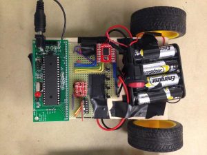
The main components of the car circuitry are the Atmega1284P, H-Bridge breakout board, motors & flyback diodes, HC-05 Bluetooth module, and voltage level converter. Notice that there is a 6V power source (4 AA batteries) for just the motors and a 9V battery to power just the microcontroller. The DC motors that were used are 3V to 6V, so the 4 AA batteries are enought to move them.
The TB6612FNG motor driver breakout board we used can supply up to 1.2A for the motors, which is enough for the DC motors to produce enough torque to move the entire car. It also contains 2 H-bridges, which is needed for our purposes to allow the car to move forward, backward, and turn by turning the direction of motors in clockwise or counterclockwise direction. The breakout board datasheet contains specifications for different modes of operation: clockwise & counterclockwise turning of motor, change of speed, and stopping the car. The table about these modes are located in the datasheet and displayed below:
We had to follow these specifications to control our motors. Ports A0 to A4 of the microcontroller control the direction in which the motor should be spinning (clockwise or counterclockwise) by controlling the voltage levels of the AIN or BIN pins of the H-bridge breakout. The STBY pin is always high when we want the motors turning. The 2 PWM signals coming from the microcontroller (ports B3 and B4) control the speed of each motor, and they go into the PWMA and PWMB pins of the motor driver board. The pins A01-2 and B01-2 are outputs of the motor driver to apply a voltage across the DC motors.
Another part of the car was the Bluetooth transceiver which will receive the commands coming from the other Bluetooth module on the remote. This Bluetooth transceiver was again directly connected to the Rx and Tx pins of the microcontroller to communicate through UART. However, for this circuit, we need to read the STATE pin of the Bluetooth to see if the transceiver somehow lost connection with the other module. We measured that the STATE pin outputs 3.3V when the Bluetooth is paired with another device and 0V when it is not paired with anything. We want the car to automatically stop if it loses communication with the master control, and the microcontroller can read this change in voltage as a interrupt and stop the car. However, the microcontroller cannot register the level of a pin as 1 unless the voltage on the pin is around 4V and above, so we had to use a voltage level shifter to shift the 3.3V to 5V so the microcontroller could detect the change in voltage. The voltage level shifter breakout board was relatively easy to use, and you had to supply it 5V and 3.3V (on HV and LV pin respectively)for it to output a 5V on pin TX0 when the input (pin TX1) was 3.3V and output 0V when input is 0V. If you didn’t supply the level shifter with 3.3V, it would always output a 5V to TX0 pin, which would never change the voltage level on pin D3.
Physical Design
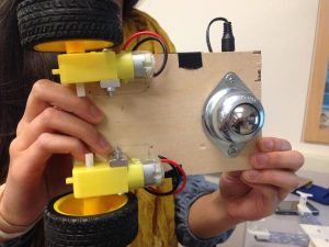
The physical design of the car involved creating a car chassis to hold all of the electronics and batteries as well as have it easily mount with the motors and wheels. The body of the car had dimensions of 7 inches by 6.25 inches, just wide and long enough to fit the two motors, the soldered board, and the microcontroller. The chassis was made of plywood and holes were drilled to allow easy mounting of the two DC motors and the third ball bearing wheel. Plywood was also strong enough to hold the microcontroller, soldered car circuit, motors, wheels, and 4 AA battery pack. Some components were significantly heavier than others, so we had to distribute the weight evenly throughout the car to prevent flipping. The battery pack was placed between the two DC motors to keep the weight in the center.
Testing
One of the main methods that we used to debug the car and remote circuitry, as well as certain components, was using UART to print out the values of variables in software. Another method that we employed was splitting up the code for distinctive modules like accelerometer sensor and Bluetooth module code before integrating all of them together. For figuring out I2C to interact with the accelerometer breakout board, we had to debug with hardware and software.
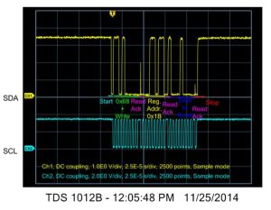
To ensure that the I2C library was working, we used the oscilloscope to display the voltage levels of the SCL and SDA lines of the microcontroller. For example, we had code that would utilize the i2c_start(), i2c_write(), and i2c_stop() methods of Peter Fleury. The sample sequence for the first oscilloscope shot below was: Start, slave’s address (0x68) + write bit (0), acknowledge, write a specific register address of the accelerometer board – WHOAMI (0x75), acknowledge, start, slave address + read bit (0), acknowledge, data from slave, not acknowledge, and stop. This sequence was requesting the contents of the WHO_AM_I register of the accelerometer board, and the slave data that was returned was 0x68, which was expected.
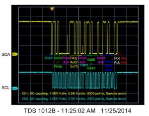
The 2nd test sequence we wrote to the accelerometer was to set the configuration of the gyroscope to full scale range of 2000 degrees/second to see if the write sequence worked. The data written to GYRO__CONFIG register was 0b00011000. It appeared that all of the signals were outputted correctly from the microcontroller to the accelerometer correctly.
Then, when we noticed that we still could not get data from the accelerometer board, we searched online and found that the board is initially asleep and needs to be woken up to send data to the microcontroller. To figure out if two Bluetooth modules were communicating data to each other, we set up two microcontrollers so that one microcontroller sent the strings “on” and “off” repeatedly, and the other microcontroller physically turned on or off a green LED to match what it received.
Once everything was put together, we tested the system as a whole. This involved first ensuring that the car’s wheels would spin when the remote was tilted. Doing this check verified that we were able to get tilt angle values to from the remote to the car. Another test was to check how quickly the car responded to the remote, which we could do by simply tilting the remote back and forth and seeing how quickly the car’s wheels changed direction. The final test of the system as a whole was the turning and maneuverability of the car. For our first iteration of the turning code, we found that there were issues with the signs of the numbers we were sending to the car, as well as not handling turns correctly when the car was going in reverse. Thorough testing of the car ensured that a user unfamiliar with the car would not be thrown off by quirks or bugs in the car’s operation.
Another important test was checking to see that the car stopped when the Bluetooth module on it got disconnected from the remote. To test this, we first tilted the remote to give the car a starting speed, then turned off the MCU on the remote (thus powering down the remote’s Bluetooth module) to see that the car eventually stopped.
Results
Speed of Execution
Our motor controller code uses TinyRealTime, so reading in information from the Bluetooth module and setting the PWM values for each motor happen in parallel.
When using the remote with the car, we found that there was no noticeable delay between when a user tilts the remote to issue a command and when the car executes the command by changing direction. Thus, though Bluetooth slows down the RF communication quite a bit, the slowness is not noticeable for our purposes.
Having such a quick speed in the controls means that our car is very interactive and not at all frustrating to use. This aspect is important because the main goal of this project was to create something that would be fun to use and interact with.
Accuracy
We found the accelerometer on the MPU-6050 to be quite sensitive, so the angles calculated from the accelerometer data had fine resolutions. While we did not compare these values to a protractor reading, we were less concerned about the accuracy of the measured angles and were mainly focused on relative angles (i.e., is the remote tilted a lot or a little?).
Additionally, the quality of the car’s turning could likely be improved, but for our purposes, we found that since a user is constantly monitoring the car and readjusting the way they control the car, our current calculations suffice. In addition, when the accelerometer was mounted onto the white solderless board, the board is not able to be mounted completely flat, thus giving a slight offset in angle of the remote.
Safety
The car is relatively small and does not achieve very great speeds, so not much harm would come to any person that the car accidentally runs into (as long as that person is wearing shoes). Nevertheless, it is important that the people around the car are aware that it is moving nearby, someone could trip if they do not see the car. Thus, our car makes a whirring sound to indicate it is running and warns people that it is closeby.
We also incorporated two types of emergency stops. The first is on the part of the remote control. If the user presses and holds the emergency stop button on the remote, then the car will almost immediately stop moving.
The second emergency stop is on the car. If the Bluetooth module on the car becomes unpaired from the module on the remote, then the car will stop. Unfortunately, we found that it takes 4 to 5 seconds for the HC-05 Bluetooth module to realize that is no longer receiving data from the other module. A lot can happen in 5 seconds, but we do not believe that there is a way to decrease this time (given the hardware that we have), and the relative low speed and small size of the car should keep anything catastrophic from happening within that time.
Interference
Since Bluetooth signals are sent over the air, there is always the possibility that our signals will interfere with someone else’s. Bluetooth also shares the same frequency band as WiFi. However, the Bluetooth protocol has been written to avoid interfering with WiFi and other Bluetooth signals, so interference should be minimal to non-existent.
Usability
The AccelCar can be used by people of all ages for pure entertainment as well as to transport small objects from one location to another. The range at which the remote can control the car is more than enough for the purposes of entertainment. Though some preliminary testing, we determined that our Bluetooth modules could communicate with no problem from the bottom of the steps of Duffield Hall to the doors of Upson Hall. We used Google Maps and the Distance Calculator tool on daftlogic.com [link] to find that this is roughly 280 ft.
The remote was specifically designed so that if the user held the remote at 10 degrees or less in magnitude, the car would not move, because it is hard for anyone to hold the remote flat perfectly. An extra feature to keep the car from randomly moving was a button which when held down, will send the stop command to the car, keeping it from moving while the user can reorient the remote however they please.
Furthermore, throughout the development of our project, we found that some of the parts we ordered had relatively sparse or difficult-to-use documentation. After finding out how to use and integrate the breakout boards and modules that we bought, we feel that our documentation (in the Appendix) adds useful information to the existing documentation available online.
One negative aspect of the car’s usability is the fact that the wheels that we used for the car are made of plastic and slip easily when dusty. This problem can easily be remedied by replacing the wheels with rubber wheels or even placing rubber bands around the wheels for more traction.
Conclusions
Our original design was a quadcopter controlled by a remote which would also send out directions and speed based on the remote’s tilt angle. Even though our project is now a car, we still maintained the same kind of controls.
The final product of our design almost fully meets our expectations for how the car should behave. The controls are quite intuitive, though some initial instruction might be needed for a new user playing with the car. Controls are also fast enough that there is no perceivable delay between when a user issues a command from the remote to when the car executes the command.
Future Work
Some ideas that could be implemented for the future would be to possibly make more than one car so it would be more like a real-life Mario Kart. Another feature that could be implemented is programming an Android smartphone to send out the commands through Bluetooth. Most smartphones have an accelerometer built in, and there is a lot of documentation online for how to interface with the accelerometer and Bluetooth, since the Android community is very open-source.
Standards
The HC-05 Bluetooth module is a prepackaged Bluetooth device and must therefore conform to the FCC regulations regarding Bluetooth and radio. Our design also uses the I2C protocol for communication between the gyroscope/accelerometer module and the MCU. For debugging, we used the RS-232 standard for serial communication between the MCU’s UART ports and a computer running PuTTY.
Intellectual Property Considerations
For this project, we referenced code from Ellen Chuang and Julie Wang (Wireless Pedometer, Fall 2013) and Brian Harding and Cat Jubinski (FaceAccess, Spring 2011). We also used Peter Fleury’s I2C Master library for the Atmega1284.
As mentioned in a previous section, U.S. Patent US8106748 describes a similar structure to the one in our project, but our project differs from the patent in that our remote control only has accelerometer sensing, with no manual input mode.
Despite all of the prior work depicted online, we designed our system from scratch and did not reverse-engineer any of the projects that we discovered online.
There are likely no patent or publishing opportunities for this project, as it is a relatively straightforward system, and many people have built similar things.
Ethical Considerations
Throughout the course of this project, in both the design and implementation stage, we adhered to the IEEE Code of Ethics.
The Code of Ethics states that we must “accept responsibility in making decisions consistent with the safety, health, and welfare of the public, and to disclose promptly factors that might endanger the public or the environment.” We accomplished this by incorporating emergency stops in our RC car’s design and by keeping the size and speed of the car to manageable values. Our decision to use FCC-compliant prepackaged Bluetooth modules further demonstrates our commitment to safety. Normal use of the car we created should not have a negative effect on people’s safety, to the best of our knowledge.
In addition, the Code states that we must aim to “improve the understanding of technology; its appropriate application, and potential consequences,” which we believe we accomplished by expanding upon the currently available documentation of the HC-05 Bluetooth module and MPU-6050 gyroscope/accelerometer module.
Lastly, the Code asks us to “seek, accept, and offer honest criticism of technical work, to acknowledge and correct errors, and to credit properly the contributions of others.” Seeking help from the course staff and correcting our errors were at the core of our work throughout this project. We also strove to adequately attribute all of the work that we referenced through our documentation.
Legal Considerations
Our project does not violate any legal restrictions, to the best of our knowledge. The communication from remote control to car is done over Bluetooth, which is a subset of RF, and is regulated therefore by the FCC. Since we are using a prepackaged Bluetooth module, it must conform to the FCC standards.
Source: AccelCar
- How does the AccelCar determine movement direction?
The car determines direction by mapping the signed tilt angles from the remote; negative angles spin wheels backward while positive angles spin them forward. - Can the AccelCar turn tighter if tilted more sideways?
Yes, a greater sideways angle decreases the speed of the inner wheel relative to the outer wheel, creating a tighter turn. - Why were DC motors chosen over servos for this project?
DC motors were chosen because they provide higher RPMs suitable for a Mario Kart style experience, whereas servos generally run slower. - What happens if the Bluetooth connection is lost?
The car automatically stops moving when it detects that the Bluetooth module has lost its connection with the remote. - How often are angle values sent from the remote to the car?
Values are sent every 100 milliseconds to avoid jitter while maintaining seamless control. - What material was used for the car body and why?
Plywood was used because it is easy to drill holes into for mounting components without requiring special bits or laser cutting. - Does the remote have a manual input mode?
No, the remote control relies solely on accelerometer sensing with no manual input mode. - What is the purpose of the voltage level shifter on the car?
The voltage level shifter converts the 3.3V signal from the Bluetooth STATE pin to 5V so the microcontroller can detect connection status changes.